Power SMS 1.3 Release 3 serial key or number

Power SMS 1.3 Release 3 serial key or number
Android version history
The version history of the Androidmobile operating system began with the public release of the Android beta on November 5, 2007. The first commercial version, Android 1.0, was released on September 23, 2008. Android is continually developed by Google and the Open Handset Alliance (OHA), and it has seen several updates to its base operating system since the initial release.
Overview[edit]
The development of Android started in 2003 by Android, Inc., which was purchased by Google in 2005.[1] There were at least two internal releases of the software inside Google and the OHA before the beta version was released.[2][3] The beta was released on November 5, 2007,[4][5] while the software development kit (SDK) was released on November 12, 2007.[6] Several public beta versions of the SDK were released.[7] These releases were done through software emulation as physical devices did not exist to test the operating system.
The first public release of Android 1.0 occurred with the release of the T-Mobile G1 (aka HTC Dream) in October 2008.[8] Android 1.0 and 1.1 were not released under specific code names. The code names "Astro Boy" and "Bender" were tagged internally on some of the early pre-1.0 milestone builds and were never used as the actual code names of the 1.0 and 1.1 releases of the OS.[9]
The project manager, Ryan Gibson, conceived using a confectionery-themed naming scheme for public releases, starting with Android 1.5 Cupcake. Google announced in August 2019 they were ending the confectionery theming scheme to use numerical ordering for future versions.[10] The first release under the numerical order format was Android 10, which was released the following month.
In 2017, Google announced that Google Play would begin to require apps to target a recent Android version.[11] Initially the minimum requirement was Android 8, released in the second half of 2017, for which support would be required for new apps by August 2018, and for updates to existing apps by November 2018. This pattern has continued in subsequent years.[12][13]
| Name | Version number(s) | Initial stable release date | Supported (security fixes) | API level | References |
|---|---|---|---|---|---|
| No official codename | 1.0 | September 23, 2008 | No | 1 | [9] |
| 1.1 | February 9, 2009 | No | 2 | [9][14] | |
| Cupcake | 1.5 | April 27, 2009 | No | 3 | [15] |
| Donut | 1.6 | September 15, 2009 | No | 4 | [16] |
| Eclair | 2.0 – 2.1 | October 26, 2009 | No | 5 – 7 | [17] |
| Froyo | 2.2 – 2.2.3 | May 20, 2010 | No | 8 | [18] |
| Gingerbread | 2.3 – 2.3.7 | December 6, 2010 | No | 9 – 10 | [19] |
| Honeycomb | 3.0 – 3.2.6 | February 22, 2011 | No | 11 – 13 | [20] |
| Ice Cream Sandwich | 4.0 – 4.0.4 | October 18, 2011 | No | 14 – 15 | [21] |
| Jelly Bean | 4.1 – 4.3.1 | July 9, 2012 | No | 16 – 18 | [22] |
| KitKat | 4.4 – 4.4.4 | October 31, 2013 | No | 19 – 20 | [23] |
| Lollipop | 5.0 – 5.1.1 | November 12, 2014 | No | 21 – 22 | [24] |
| Marshmallow | 6.0 – 6.0.1 | October 5, 2015 | No | 23 | [25] |
| Nougat | 7.0 – 7.1.2 | August 22, 2016 | No | 24 – 25 | [26][27][28][29] |
| Oreo | 8.0 – 8.1 | August 21, 2017 | Yes | 26 – 27 | [30] |
| Pie | 9 | August 6, 2018 | Yes | 28 | [31] |
| Android 10 | 10 | September 3, 2019 | Yes | 29 | [32] |
| Android 11 | 11 | September 8, 2020 | Yes | 30 | [33] |
Version history by API level[edit]
The following tables show the release dates and key features of all Android operating system updates to date, listed chronologically by their official application programming interface (API) levels.
| Android 1.0 (API 1) | ||
|---|---|---|
| Android 1.0, the first commercial version of the software, was released on September 23, 2008.[34] The first commercially available Android device was the HTC Dream.[35] Android 1.0 incorporated the following features: | ||
| Version | Release date | Features |
| 1.0 | September 23, 2008 |
|
| Android 1.1 (API 2) | ||
|---|---|---|
| On February 9, 2009, the Android 1.1 update was released, initially for the HTC Dream only. Android 1.1 was known as "Petit Four" internally, though this name was not used officially.[9][42] The update resolved bugs, changed the Android API and added a number of features:[43] | ||
| Version | Release date | Features |
| 1.1 | February 9, 2009 |
|
| Android 1.5 Cupcake (API 3) | |||
|---|---|---|---|
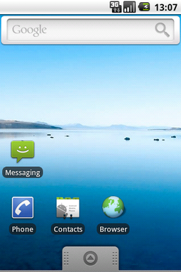
| On April 27, 2009, the Android 1.5 update was released, based on Linux kernel 2.6.27.[44][45] This was the first release to officially use a codename based on a dessert item ("Cupcake"), a theme used for all releases until Android Pie, with Android 10 using a number-only system. The update included several new features and UI amendments:[46] | |||
| Version | Release date | Features | Image(s) |
| 1.5 | April 27, 2009[44] |
|  Android 1.5 home screen |
| Android 1.6 Donut (API 4) | |||
|---|---|---|---|
| On September 15, 2009, Android 1.6 – dubbed Donut – was released, based on Linux kernel 2.6.29.[49][50][51] Included in the update were numerous new features:[49] | |||
| Version | Release date | Features | Image(s) |
| 1.6 | September 15, 2009[50] |
|  Android 1.6 home screen |
| Android 2.0 Eclair (API 5) | |||
|---|---|---|---|
| On October 26, 2009, the Android 2.0 SDK was released, based on Linux kernel 2.6.29 and codenamed Eclair.[52] Changes include the ones listed below.[53] | |||
| Version | Release date | Features | Image(s) |
| 2.0 | October 26, 2009 |
|  Android 2.0 home screen |
| Android 2.2 Froyo (API 8) | |||
|---|---|---|---|
| On May 20, 2010, the SDK for Android 2.2 (Froyo, short for frozen yogurt) was released, based on Linux kernel 2.6.32.[58] | |||
| Version | Release date | Features | Image(s) |
| 2.2 | May 20, 2010 |
|  Android 2.2 home screen |
| 2.2.1 | January 18, 2011 |
| |
| 2.2.2 | January 22, 2011 | ||
| 2.2.3 | November 21, 2011[67] | ||
| Android 2.3 Gingerbread (API 9) | |||
|---|---|---|---|
| On December 6, 2010, the Android 2.3 (Gingerbread) SDK was released, based on Linux kernel 2.6.35.[68][69] Changes included:[68] | |||
| Version | Release date | Features | Image(s) |
| 2.3 | December 6, 2010[69] |
|  Android 2.3 home screen |
| 2.3.1 | December 2010 |
| |
| 2.3.2 | January 2011 |
| |
| Android 3.0 Honeycomb (API 11) | |||
|---|---|---|---|
| On February 22, 2011, the Android 3.0 (Honeycomb) SDK – the first tablet-only Android update – was released, based on Linux kernel 2.6.36.[82][83][84][85] The first device featuring this version, the Motorola Xoom tablet, was released on February 24, 2011.[86] The update's features included:[82] | |||
| Version | Release date | Features | Image(s) |
| 3.0 | February 22, 2011[84] |
|  Android 3.0 home screen |
| Android 3.1 Honeycomb (API 12) | |||
|---|---|---|---|
| Version | Release date | Features | Image(s) |
| 3.1 | May 10, 2011[90] |
| |
| Android 3.2 Honeycomb (API 13) | |||
|---|---|---|---|
| Version | Release date | Features | Image(s) |
| 3.2 | July 15, 2011[93] |
| |
| 3.2.1 | September 20, 2011 |
| |
| 3.2.2 | August 30, 2011 |
| |
| 3.2.3 | August 30, 2011[94][93][93] |
| |
| 3.2.4 | December 2011 |
| |
| 3.2.5 | January 2012 |
| |
| 3.2.6 | February 2012 |
| |
| Android 4.0 Ice Cream Sandwich (API 14) | |||
|---|---|---|---|
| The SDK for Android 4.0.1 (Ice Cream Sandwich), based on Linux kernel 3.0.1,[95] was publicly released on October 19, 2011.[96] Google's Gabe Cohen stated that Android 4.0 was "theoretically compatible" with any Android 2.3.x device in production at that time.[97] The source code for Android 4.0 became available on November 14, 2011.[98] Ice Cream Sandwich was the last version to officially support Adobe Systems' Flash player.[99] The update introduced numerous new features:[100][101][102] | |||
| Version | Release date | Features | Image(s) |
| 4.0 | October 18, 2011[100] |
| 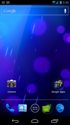 Android 4.0 home screen |
| 4.0.1 | October 21, 2011 |
| |
| 4.0.2 | November 28, 2011 |
| |
| Android 4.0.3 Ice Cream Sandwich (API 15) | |||
|---|---|---|---|
| Version | Release date | Features | Image(s) |
| 4.0.3 | December 16, 2011[108] |
| |
| 4.0.4 | March 29, 2012[110] |
| |
| Android 4.1 Jelly Bean (API 16) | |||
|---|---|---|---|
| Google announced Android 4.1 (Jelly Bean) at the Google I/O conference on June 27, 2012. Based on Linux kernel 3.0.31, Jelly Bean was an incremental update with the primary aim of improving the functionality and performance of the user interface. The performance improvement involved "Project Butter", which uses touch anticipation, triple buffering, extended vsync timing and a fixed frame rate of 60 fps to create a fluid and "buttery-smooth" UI.[112] Android 4.1 Jelly Bean was released to the Android Open Source Project on July 9, 2012,[113] and the Nexus 7 tablet, the first device to run Jelly Bean, was released on July 13, 2012. | |||
| Version | Release date | Features | Image(s) |
| 4.1 | July 9, 2012 |
|  Android 4.1 home screen |
| 4.1.1 | July 11, 2012[117] |
| |
| 4.1.2 | October 9, 2012[118] |
| |
| Android 4.2 Jelly Bean (API 17) | ||
|---|---|---|
| Google was expected to announce Jelly Bean 4.2 at an event in New York City on October 29, 2012, but the event was cancelled due to Hurricane Sandy.[121] Instead of rescheduling the live event, Google announced the new version with a press release, under the slogan "A new flavor of Jelly Bean". Jelly Bean 4.2 was based on Linux kernel 3.4.0, and debuted on Google's Nexus 4 and Nexus 10, which were released on November 13, 2012.[122][123] | ||
| Version | Release date | Features |
| 4.2 | November 13, 2012[124] |
|
| 4.2.1 | November 27, 2012[129] |
|
| 4.2.2 | February 11, 2013[131] |
|
| Android 4.3 Jelly Bean (API 18) | ||
|---|---|---|
| Google released Jelly Bean 4.3 under the slogan "An even sweeter Jelly Bean" on July 24, 2013, during an event in San Francisco called "Breakfast with Sundar Pichai". Most Nexus devices received the update within a week, although the second-generation Nexus 7 tablet was the first device to officially ship with it.[133] A minor bug fix update was released on August 22, 2013.[134] | ||
| Version | Release date | Features |
| 4.3 | July 24, 2013[135] | |
| 4.3.1 | October 3, 2013[144] | |
| Android 4.4 KitKat (API 19) | |||
|---|---|---|---|
| Google announced Android 4.4 KitKat on September 3, 2013. Although initially under the "Key Lime Pie" ("KLP") codename, the name was changed because "very few people actually know the taste of a key lime pie."[146] Some technology bloggers also expected the "Key Lime Pie" release to be Android 5.[147] KitKat debuted on Google's Nexus 5 on October 31, 2013, and was optimized to run on a greater range of devices than earlier Android versions, having 512 MB of RAM as a recommended minimum; those improvements were known as "Project Svelte" internally at Google.[148] The required minimum amount of RAM available to Android is 340 MB, and all devices with less than 512 MB of RAM must report themselves as "low RAM" devices.[149] | |||
| Version | Release date | Features | Image(s) |
| 4.4 | October 31, 2013[150][151] |
| |
Android 11 Compatibility Definition
1. Introduction
This document enumerates the requirements that must be met in order for devices to be compatible with Android 11.
The use of “MUST”, “MUST NOT”, “REQUIRED”, “SHALL”, “SHALL NOT”, “SHOULD”, “SHOULD NOT”, “RECOMMENDED”, “MAY”, and “OPTIONAL” is per the IETF standard defined in RFC2119.
As used in this document, a “device implementer” or “implementer” is a person or organization developing a hardware/software solution running Android 11. A “device implementation” or “implementation" is the hardware/software solution so developed.
To be considered compatible with Android 11, device implementations MUST meet the requirements presented in this Compatibility Definition, including any documents incorporated via reference.
Where this definition or the software tests described in section 10 is silent, ambiguous, or incomplete, it is the responsibility of the device implementer to ensure compatibility with existing implementations.
For this reason, the Android Open Source Project is both the reference and preferred implementation of Android. Device implementers are STRONGLY RECOMMENDED to base their implementations to the greatest extent possible on the “upstream” source code available from the Android Open Source Project. While some components can hypothetically be replaced with alternate implementations, it is STRONGLY RECOMMENDED to not follow this practice, as passing the software tests will become substantially more difficult. It is the implementer’s responsibility to ensure full behavioral compatibility with the standard Android implementation, including and beyond the Compatibility Test Suite. Finally, note that certain component substitutions and modifications are explicitly forbidden by this document.
Many of the resources linked to in this document are derived directly or indirectly from the Android SDK and will be functionally identical to the information in that SDK’s documentation. In any cases where this Compatibility Definition or the Compatibility Test Suite disagrees with the SDK documentation, the SDK documentation is considered authoritative. Any technical details provided in the linked resources throughout this document are considered by inclusion to be part of this Compatibility Definition.
1.1 Document Structure
1.1.1. Requirements by Device Type
Section 2 contains all of the requirements that apply to a specific device type. Each subsection of Section 2 is dedicated to a specific device type.
All the other requirements, that universally apply to any Android device implementations, are listed in the sections after Section 2. These requirements are referenced as "Core Requirements" in this document.
1.1.2. Requirement ID
Requirement ID is assigned for MUST requirements.
- The ID is assigned for MUST requirements only.
- STRONGLY RECOMMENDED requirements are marked as [SR] but ID is not assigned.
- The ID consists of : Device Type ID - Condition ID - Requirement ID (e.g. C-0-1).
Each ID is defined as below:
- Device Type ID (see more in 2. Device Types)
- C: Core (Requirements that are applied to any Android device implementations)
- H: Android Handheld device
- T: Android Television device
- A: Android Automotive implementation
- W: Android Watch implementation
- Tab: Android Tablet implementation
- Condition ID
- When the requirement is unconditional, this ID is set as 0.
- When the requirement is conditional, 1 is assigned for the 1st condition and the number increments by 1 within the same section and the same device type.
- Requirement ID
- This ID starts from 1 and increments by 1 within the same section and the same condition.
1.1.3. Requirement ID in Section 2
The Requirement ID in Section 2 starts with the corresponding section ID that is followed by the Requirement ID described above.
- The ID in Section 2 consists of : Section ID / Device Type ID - Condition ID - Requirement ID (e.g. 7.4.3/A-0-1).
2. Device Types
While the Android Open Source Project provides a software stack that can be used for a variety of device types and form factors, there are a few device types that have a relatively better established application distribution ecosystem.
This section describes those device types, and additional requirements and recommendations applicable for each device type.
All Android device implementations that do not fit into any of the described device types MUST still meet all requirements in the other sections of this Compatibility Definition.
2.1 Device Configurations
For the major differences in hardware configuration by device type, see the device-specific requirements that follow in this section.
2.2. Handheld Requirements
An Android Handheld device refers to an Android device implementation that is typically used by holding it in the hand, such as an mp3 player, phone, or tablet.
Android device implementations are classified as a Handheld if they meet all the following criteria:
- Have a power source that provides mobility, such as a battery.
- Have a physical diagonal screen size in the range of 3.3 inches (or 2.5 inches for devices which launched on an API level earlier than Android 11) to 8 inches.
The additional requirements in the rest of this section are specific to Android Handheld device implementations.
2.2.1. Hardware
Handheld device implementations:
- [7.1.1.1/H-0-1] MUST have at least one Android-compatible display that meets all requirements described on this document.
- [7.1.1.3/H-SR] Are STRONGLY RECOMMENDED to provide users an affordance to change the display size (screen density).
If Handheld device implementations support software screen rotation, they:
- [7.1.1.1/H-1-1]* MUST make the logical screen that is made available for third party applications be at least 2 inches on the short edge(s) and 2.7 inches on the long edge(s). Devices which launched on an API level earlier than that of this document are exempted from this requirement.
If Handheld device implementations do not support software screen rotation, they:
- [7.1.1.1/H-2-1]* MUST make the logical screen that is made available for third party applications be at least 2.7 inches on the short edge(s). Devices which launched on an API level earlier than that of this document are exempted from this requirement.
If Handheld device implementations claim support for high dynamic range displays through , they:
- [7.1.4.5/H-1-1] MUST advertise support for the , , , , and extensions.
Handheld device implementations:
- [7.1.4.6/H-0-1] MUST report whether the device supports the GPU profiling capability via a system property .
If Handheld device implementations declare support via a system property , they:
Handheld device implementations:
- [7.1.5/H-0-1] MUST include support for legacy application compatibility mode as implemented by the upstream Android open source code. That is, device implementations MUST NOT alter the triggers or thresholds at which compatibility mode is activated, and MUST NOT alter the behavior of the compatibility mode itself.
- [7.2.1/H-0-1] MUST include support for third-party Input Method Editor (IME) applications.
- [7.2.3/H-0-3] MUST provide the Home function on all the Android-compatible displays that provide the home screen.
- [7.2.3/H-0-4] MUST provide the Back function on all the Android-compatible displays and the Recents function on at least one of the Android-compatible displays.
- [7.2.3/H-0-2] MUST send both the normal and long press event of the Back function () to the foreground application. These events MUST NOT be consumed by the system and CAN be triggered by outside of the Android device (e.g. external hardware keyboard connected to the Android device).
- [7.2.4/H-0-1] MUST support touchscreen input.
- [7.2.4/H-SR] Are STRONGLY RECOMMENDED to launch the user-selected assist app, in other words the app that implements VoiceInteractionService, or an activity handling the on long-press of or if the foreground activity does not handle those long-press events.
- [7.3.1/H-SR] Are STRONGLY RECOMMENDED to include a 3-axis accelerometer.
If Handheld device implementations include a 3-axis accelerometer, they:
- [7.3.1/H-1-1] MUST be able to report events up to a frequency of at least 100 Hz.
If Handheld device implementations include a GPS/GNSS receiver and report the capability to applications through the feature flag, they:
- [7.3.3/H-2-1] MUST report GNSS measurements, as soon as they are found, even if a location calculated from GPS/GNSS is not yet reported.
- [7.3.3/H-2-2] MUST report GNSS pseudoranges and pseudorange rates, that, in open-sky conditions after determining the location, while stationary or moving with less than 0.2 meter per second squared of acceleration, are sufficient to calculate position within 20 meters, and speed within 0.2 meters per second, at least 95% of the time.
If Handheld device implementations include a 3-axis gyroscope, they:
- [7.3.4/H-3-1] MUST be able to report events up to a frequency of at least 100 Hz.
- [7.3.4/H-3-2] MUST be capable of measuring orientation changes up to 1000 degrees per second.
Handheld device implementations that can make a voice call and indicate any value other than in :
- [7.3.8/H] SHOULD include a proximity sensor.
Handheld device implementations:
- [7.3.11/H-SR] Are RECOMMENDED to support pose sensor with 6 degrees of freedom.
- [7.4.3/H] SHOULD include support for Bluetooth and Bluetooth LE.
If Handheld device implementations include a metered connection, they:
- [7.4.7/H-1-1] MUST provide the data saver mode.
If Handheld device implementations include a logical camera device that lists capabilities using , they:
- [7.5.4/H-1-1] MUST have normal field of view (FOV) by default and it MUST be between 50 and 90 degrees.
Handheld device implementations:
- [7.6.1/H-0-1] MUST have at least 4 GB of non-volatile storage available for application private data (a.k.a. "/data" partition).
- [7.6.1/H-0-2] MUST return “true” for when there is less than 1GB of memory available to the kernel and userspace.
If Handheld device implementations declare support of only a 32-bit ABI:
[7.6.1/H-1-1] The memory available to the kernel and userspace MUST be at least 416MB if the default display uses framebuffer resolutions up to qHD (e.g. FWVGA).
[7.6.1/H-2-1] The memory available to the kernel and userspace MUST be at least 592MB if the default display uses framebuffer resolutions up to HD+ (e.g. HD, WSVGA).
[7.6.1/H-3-1] The memory available to the kernel and userspace MUST be at least 896MB if the default display uses framebuffer resolutions up to FHD (e.g. WSXGA+).
[7.6.1/H-4-1] The memory available to the kernel and userspace MUST be at least 1344MB if the default display uses framebuffer resolutions up to QHD (e.g. QWXGA).
If Handheld device implementations declare support of 32-bit and 64-bit ABIs:
[7.6.1/H-5-1] The memory available to the kernel and userspace MUST be at least 816MB if the default display uses framebuffer resolutions up to qHD (e.g. FWVGA).
[7.6.1/H-6-1] The memory available to the kernel and userspace MUST be at least 944MB if the default display uses framebuffer resolutions up to HD+ (e.g. HD, WSVGA).
[7.6.1/H-7-1] The memory available to the kernel and userspace MUST be at least 1280MB if the default display uses framebuffer resolutions up to FHD (e.g. WSXGA+).
[7.6.1/H-8-1] The memory available to the kernel and userspace MUST be at least 1824MB if the default display uses framebuffer resolutions up to QHD (e.g. QWXGA).
Note that the "memory available to the kernel and userspace" above refers to the memory space provided in addition to any memory already dedicated to hardware components such as radio, video, and so on that are not under the kernel’s control on device implementations.
If Handheld device implementations include less than or equal to 1GB of memory available to the kernel and userspace, they:
- [7.6.1/H-9-1] MUST declare the feature flag .
- [7.6.1/H-9-2] MUST have at least 1.1 GB of non-volatile storage for application private data (a.k.a. "/data" partition).
If Handheld device implementations include more than 1GB of memory available to the kernel and userspace, they:
- [7.6.1/H-10-1] MUST have at least 4GB of non-volatile storage available for application private data (a.k.a. "/data" partition).
- SHOULD declare the feature flag .
Handheld device implementations:
- [7.6.2/H-0-1] MUST NOT provide an application shared storage smaller than 1 GiB.
- [7.7.1/H] SHOULD include a USB port supporting peripheral mode.
If handheld device implementations include a USB port supporting peripheral mode, they:
- [7.7.1/H-1-1] MUST implement the Android Open Accessory (AOA) API.
If Handheld device implementations include a USB port supporting host mode, they:
- [7.7.2/H-1-1] MUST implement the USB audio class as documented in the Android SDK documentation.
Handheld device implementations:
- [7.8.1/H-0-1] MUST include a microphone.
- [7.8.2/H-0-1] MUST have an audio output and declare .
If Handheld device implementations are capable of meeting all the performance requirements for supporting VR mode and include support for it, they:
- [7.9.1/H-1-1] MUST declare the feature flag.
- [7.9.1/H-1-2] MUST include an application implementing that can be enabled by VR applications via .
If Handheld device implementations include one or more USB-C port(s) in host mode and implement (USB audio class), in addition to requirements in section 7.7.2, they:
- [7.8.2.2/H-1-1] MUST provide the following software mapping of HID codes:
| Function | Mappings | Context | Behavior |
|---|---|---|---|
| A | HID usage page: 0x0C HID usage: 0x0CD Kernel key: Android key: | Media playback | Input: Short press Output: Play or pause |
| Input: Long press Output: Launch voice command Sends: if the device is locked or its screen is off. Sends otherwise | |||
| Incoming call | Input: Short press Output: Accept call | ||
| Input: Long press Output: Reject call | |||
| Ongoing call | Input: Short press Output: End call | ||
| Input: Long press Output: Mute or unmute microphone | |||
| B | HID usage page: 0x0C HID usage: 0x0E9 Kernel key: Android key: | Media playback, Ongoing call | Input: Short or long press Output: Increases the system or headset volume |
| C | HID usage page: 0x0C HID usage: 0x0EA Kernel key: Android key: | Media playback, Ongoing call | Input: Short or long press Output: Decreases the system or headset volume |
| D | HID usage page: 0x0C HID usage: 0x0CF Kernel key: Android key: | All. Can be triggered in any instance. | Input: Short or long press Output: Launch voice command |
- [7.8.2.2/H-1-2] MUST trigger ACTION_HEADSET_PLUG upon a plug insert, but only after the USB audio interfaces and endpoints have been properly enumerated in order to identify the type of terminal connected.
When the USB audio terminal types 0x0302 is detected, they:
- [7.8.2.2/H-2-1] MUST broadcast Intent ACTION_HEADSET_PLUG with "microphone" extra set to 0.
When the USB audio terminal types 0x0402 is detected, they:
- [7.8.2.2/H-3-1] MUST broadcast Intent ACTION_HEADSET_PLUG with "microphone" extra set to 1.
When API AudioManager.getDevices() is called while the USB peripheral is connected they:
[7.8.2.2/H-4-1] MUST list a device of type AudioDeviceInfo.TYPE_USB_HEADSET and role isSink() if the USB audio terminal type field is 0x0302.
[7.8.2.2/H-4-2] MUST list a device of type AudioDeviceInfo.TYPE_USB_HEADSET and role isSink() if the USB audio terminal type field is 0x0402.
[7.8.2.2/H-4-3] MUST list a device of type AudioDeviceInfo.TYPE_USB_HEADSET and role isSource() if the USB audio terminal type field is 0x0402.
[7.8.2.2/H-4-4] MUST list a device of type AudioDeviceInfo.TYPE_USB_DEVICE and role isSink() if the USB audio terminal type field is 0x603.
[7.8.2.2/H-4-5] MUST list a device of type AudioDeviceInfo.TYPE_USB_DEVICE and role isSource() if the USB audio terminal type field is 0x604.
[7.8.2.2/H-4-6] MUST list a device of type AudioDeviceInfo.TYPE_USB_DEVICE and role isSink() if the USB audio terminal type field is 0x400.
[7.8.2.2/H-4-7] MUST list a device of type AudioDeviceInfo.TYPE_USB_DEVICE and role isSource() if the USB audio terminal type field is 0x400.
[7.8.2.2/H-SR] Are STRONGLY RECOMMENDED upon connection of a USB-C audio peripheral, to perform enumeration of USB descriptors, identify terminal types and broadcast Intent ACTION_HEADSET_PLUG in less than 1000 milliseconds.
If Handheld device implementations include at least one haptic actuator, they:
- [7.10/H-SR]* Are STRONGLY RECOMMENDED NOT to use an eccentric rotating mass (ERM) haptic actuator(vibrator).
- [7.10/H]* SHOULD position the placement of the actuator near the location where the device is typically held or touched by hands.
- [7.10/H-SR]* Are STRONGLY RECOMMENDED to implement all public constants for clear haptics in android.view.HapticFeedbackConstants namely (CLOCK_TICK, CONTEXT_CLICK, KEYBOARD_PRESS, KEYBOARD_RELEASE, KEYBOARD_TAP, LONG_PRESS, TEXT_HANDLE_MOVE, VIRTUAL_KEY, VIRTUAL_KEY_RELEASE, CONFIRM, REJECT, GESTURE_START and GESTURE_END).
- [7.10/H-SR]* Are STRONGLY RECOMMENDED to implement all public constants for clear haptics in android.os.VibrationEffect namely (EFFECT_TICK, EFFECT_CLICK, EFFECT_HEAVY_CLICK and EFFECT_DOUBLE_CLICK) and all public constants for rich haptics in android.os.VibrationEffect.Composition namely (PRIMITIVE_CLICK and PRIMITIVE_TICK).
- [7.10/H-SR]* Are STRONGLY RECOMMENDED to use these linked haptic constants mappings.
- [7.10/H-SR]* Are STRONGLY RECOMMENDED to follow quality assessment for createOneShot() and createWaveform() API's.
- [7.10/H-SR]* Are STRONGLY RECOMMENDED to verify the capabilities for amplitude scalability by running android.os.Vibrator.hasAmplitudeControl().
Linear resonant actuator (LRA) is a single mass spring system which has a dominant resonant frequency where the mass translates in the direction of desired motion.
If Handheld device implementations include at least one linear resonant actuator, they:
- [7.10/H]* SHOULD move the haptic actuator in the X-axis of portrait orientation.
If Handheld device implementations have a haptic actuator which is X-axis Linear resonant actuator (LRA), they:
- [7.10/H-SR]* Are STRONGLY RECOMMENDED to have the resonant frequency of the X-axis LRA be under 200 Hz.
If handheld device implementations follow haptic constants mapping, they:
2.2.2. Multimedia
Handheld device implementations MUST support the following audio encoding and decoding formats and make them available to third-party applications:
- [5.1/H-0-1] AMR-NB
- [5.1/H-0-2] AMR-WB
- [5.1/H-0-3] MPEG-4 AAC Profile (AAC LC)
- [5.1/H-0-4] MPEG-4 HE AAC Profile (AAC+)
- [5.1/H-0-5] AAC ELD (enhanced low delay AAC)
Handheld device implementations MUST support the following video encoding formats and make them available to third-party applications:
- [5.2/H-0-1] H.264 AVC
- [5.2/H-0-2] VP8
Handheld device implementations MUST support the following video decoding formats and make them available to third-party applications:
- [5.3/H-0-1] H.264 AVC
- [5.3/H-0-2] H.265 HEVC
- [5.3/H-0-3] MPEG-4 SP
- [5.3/H-0-4] VP8
- [5.3/H-0-5] VP9
2.2.3. Software
Handheld device implementations:
- [3.2.3.1/H-0-1] MUST have an application that handles the , , , and intents as described in the SDK documents, and provide the user affordance to access the document provider data by using API.
- [3.2.3.1/H-0-2]* MUST preload one or more applications or service components with an intent handler, for all the public intent filter patterns defined by the following application intents listed here.
- [3.2.3.1/H-SR] Are STRONGLY RECOMMENDED to preload an email application which can handle ACTION_SENDTO or ACTION_SEND or ACTION_SEND_MULTIPLE intents to send an email.
- [3.4.1/H-0-1] MUST provide a complete implementation of the API.
- [3.4.2/H-0-1] MUST include a standalone Browser application for general user web browsing.
- [3.8.1/H-SR] Are STRONGLY RECOMMENDED to implement a default launcher that supports in-app pinning of shortcuts, widgets and widgetFeatures.
- [3.8.1/H-SR] Are STRONGLY RECOMMENDED to implement a default launcher that provides quick access to the additional shortcuts provided by third-party apps through the ShortcutManager API.
- [3.8.1/H-SR] Are STRONGLY RECOMMENDED to include a default launcher app that shows badges for the app icons.
- [3.8.2/H-SR] Are STRONGLY RECOMMENDED to support third-party app widgets.
- [3.8.3/H-0-1] MUST allow third-party apps to notify users of notable events through the and API classes.
- [3.8.3/H-0-2] MUST support rich notifications.
- [3.8.3/H-0-3] MUST support heads-up notifications.
- [3.8.3/H-0-4] MUST include a notification shade, providing the user the ability to directly control (e.g. reply, snooze, dismiss, block) the notifications through user affordance such as action buttons or the control panel as implemented in the AOSP.
- [3.8.3/H-0-5] MUST display the choices provided through in the notification shade.
- [3.8.3/H-SR] Are STRONGLY RECOMMENDED to display the first choice provided through in the notification shade without additional user interaction.
- [3.8.3/H-SR] Are STRONGLY RECOMMENDED to display all the choices provided through in the notification shade when the user expands all notifications in the notification shade.
- [3.8.3.1/H-SR] Are STRONGLY RECOMMENDED to display actions for which is set as in-line with the replies displayed by .
- [3.8.4/H-SR] Are STRONGLY RECOMMENDED to implement an assistant on the device to handle the Assist action.
If Handheld device implementations support Assist action, they:
- [3.8.4/H-SR] Are STRONGLY RECOMMENDED to use long press on key as the designated interaction to launch the assist app as described in section 7.2.3. MUST launch the user-selected assist app, in other words the app that implements , or an activity handling the intent.
If Handheld device implementations support and group them into a separate section from alerting and silent non-conversation notifications, they:
- [3.8.4/H-1-1]* MUST display conversation notifications ahead of non conversation notifications with the exception of ongoing foreground service notifications and importance:high notifications.
If Android Handheld device implementations support a lock screen, they:
- [3.8.10/H-1-1] MUST display the Lock screen Notifications including the Media Notification Template.
If Handheld device implementations support a secure lock screen, they:
- [3.9/H-1-1] MUST implement the full range of device administration policies defined in the Android SDK documentation.
- [3.9/H-1-2] MUST declare the support of managed profiles via the feature flag, except when the device is configured so that it would report itself as a low RAM device or so that it allocates internal (non-removable) storage as shared storage.
If Handheld device implementations include support for and APIs and allow third-party applications to publish , then they:
- [3.8.16/H-1-1] MUST declare the feature flag and set it to .
- [3.8.16/H-1-2] MUST provide a user affordance with the ability to add, edit, select, and operate the user’s favorite device controls from the controls registered by the third-party applications through the and the APIs.
- [3.8.16/H-1-3] MUST provide access to this user affordance within three interactions from a default Launcher.
- [3.8.16/H-1-4] MUST accurately render in this user affordance the name and icon of each third-party app that provides controls via the API as well as any specified fields provided by the APIs.
Conversely, If Handheld device implementations do not implement such controls, they:
Handheld device implementations:
- [3.10/H-0-1] MUST support third-party accessibility services.
- [3.10/H-SR] Are STRONGLY RECOMMENDED to preload accessibility services on the device comparable with or exceeding functionality of the Switch Access and TalkBack (for languages supported by the preinstalled Text-to-speech engine) accessibility services as provided in the talkback open source project.
- [3.11/H-0-1] MUST support installation of third-party TTS engines.
- [3.11/H-SR] Are STRONGLY RECOMMENDED to include a TTS engine supporting the languages available on the device.
- [3.13/H-SR] Are STRONGLY RECOMMENDED to include a Quick Settings UI component.
If Android handheld device implementations declare or support, they:
- [3.16/H-1-1] MUST support the companion device pairing feature.
If the navigation function is provided as an on-screen, gesture-based action:
- [7.2.3/H] The gesture recognition zone for the Home function SHOULD be no higher than 32 dp in height from the bottom of the screen.
If Handheld device implementations provide a navigation function as a gesture from anywhere on the left and right edges of the screen:
- [7.2.3/H-0-1] The navigation function's gesture area MUST be less than 40 dp in width on each side. The gesture area SHOULD be 24 dp in width by default.
2.2.4. Performance and Power
- [8.1/H-0-1] Consistent frame latency. Inconsistent frame latency or a delay to render frames MUST NOT happen more often than 5 frames in a second, and SHOULD be below 1 frames in a second.
- [8.1/H-0-2] User interface latency. Device implementations MUST ensure low latency user experience by scrolling a list of 10K list entries as defined by the Android Compatibility Test Suite (CTS) in less than 36 secs.
- [8.1/H-0-3] Task switching. When multiple applications have been launched, re-launching an already-running application after it has been launched MUST take less than 1 second.
Handheld device implementations:
- [8.2/H-0-1] MUST ensure a sequential write performance of at least 5 MB/s.
- [8.2/H-0-2] MUST ensure a random write performance of at least 0.5 MB/s.
- [8.2/H-0-3] MUST ensure a sequential read performance of at least 15 MB/s.
- [8.2/H-0-4] MUST ensure a random read performance of at least 3.5 MB/s.
If Handheld device implementations include features to improve device power management that are included in AOSP or extend the features that are included in AOSP, they:
- [8.3/H-1-1] MUST provide user affordance to enable and disable the battery saver feature.
- [8.3/H-1-2] MUST provide user affordance to display all apps that are exempted from App Standby and Doze power-saving modes.
Handheld device implementations:
- [8.4/H-0-1] MUST provide a per-component power profile that defines the current consumption value for each hardware component and the approximate battery drain caused by the components over time as documented in the Android Open Source Project site.
- [8.4/H-0-2] MUST report all power consumption values in milliampere hours (mAh).
- [8.4/H-0-3] MUST report CPU power consumption per each process's UID. The Android Open Source Project meets the requirement through the kernel module implementation.
- [8.4/H-0-4] MUST make this power usage available via the shell command to the app developer.
- [8.4/H] SHOULD be attributed to the hardware component itself if unable to attribute hardware component power usage to an application.
If Handheld device implementations include a screen or video output, they:
2.2.5. Security Model
Handheld device implementations:
- [9.1/H-0-1] MUST allow third-party apps to access the usage statistics via the permission and provide a user-accessible mechanism to grant or revoke access to such apps in response to the intent.
Handheld device implementations (* Not applicable for Tablet):
- [9.11/H-0-2]* MUST back up the keystore implementation with an isolated execution environment.
- [9.11/H-0-3]* MUST have implementations of RSA, AES, ECDSA, and HMAC cryptographic algorithms and MD5, SHA1, and SHA-2 family hash functions to properly support the Android Keystore system's supported algorithms in an area that is securely isolated from the code running on the kernel and above. Secure isolation MUST block all potential mechanisms by which kernel or userspace code might access the internal state of the isolated environment, including DMA. The upstream Android Open Source Project (AOSP) meets this requirement by using the Trusty implementation, but another ARM TrustZone-based solution or a third-party reviewed secure implementation of a proper hypervisor-based isolation are alternative options.
- [9.11/H-0-4]* MUST perform the lock screen authentication in the isolated execution environment and only when successful, allow the authentication-bound keys to be used. Lock screen credentials MUST be stored in a way that allows only the isolated execution environment to perform lock screen authentication. The upstream Android Open Source Project provides the Gatekeeper Hardware Abstraction Layer (HAL) and Trusty, which can be used to satisfy this requirement.
- [9.11/H-0-5]* MUST support key attestation where the attestation signing key is protected by secure hardware and signing is performed in secure hardware. The attestation signing keys MUST be shared across large enough number of devices to prevent the keys from being used as device identifiers. One way of meeting this requirement is to share the same attestation key unless at least 100,000 units of a given SKU are produced. If more than 100,000 units of an SKU are produced, a different key MAY be used for each 100,000 units.
Note that if a device implementation is already launched on an earlier Android version, such a device is exempted from the requirement to have a keystore backed by an isolated execution environment and support the key attestation, unless it declares the feature which requires a keystore backed by an isolated execution environment.
When Handheld device implementations support a secure lock screen, they:
- [9.11/H-1-1] MUST allow the user to choose the shortest sleep timeout, that is a transition time from the unlocked to the locked state, as 15 seconds or less.
- [9.11/H-1-2] MUST provide user affordance to hide notifications and disable all forms of authentication except for the primary authentication described in 9.11.1 Secure Lock Screen. The AOSP meets the requirement as lockdown mode.
2.2.6. Developer Tools and Options Compatibility
Handheld device implementations (* Not applicable for Tablet):
- [6.1/H-0-1]* MUST support the shell command .
Handheld device implementations (* Not applicable for Tablet):
- Perfetto
- [6.1/H-0-2]* MUST expose a binary to the shell user which cmdline complies with the perfetto documentation.
- [6.1/H-0-3]* The perfetto binary MUST accept as input a protobuf config that complies with the schema defined in the perfetto documentation.
- [6.1/H-0-4]* The perfetto binary MUST write as output a protobuf trace that complies with the schema defined in the perfetto documentation.
- [6.1/H-0-5]* MUST provide, through the perfetto binary, at least the data sources described in the perfetto documentation.
- [6.1/H-0-6]* The perfetto traced daemon MUST be enabled by default (system property ).
2.3. Television Requirements
An Android Television device refers to an Android device implementation that is an entertainment interface for consuming digital media, movies, games, apps, and/or live TV for users sitting about ten feet away (a “lean back” or “10-foot user interface”).
Android device implementations are classified as a Television if they meet all the following criteria:
- Have provided a mechanism to remotely control the rendered user interface on the display that might sit ten feet away from the user.
- Have an embedded screen display with the diagonal length larger than 24 inches OR include a video output port, such as VGA, HDMI, DisplayPort, or a wireless port for display.
The additional requirements in the rest of this section are specific to Android Television device implementations.
2.3.1. Hardware
Television device implementations:
- [7.2.2/T-0-1] MUST support D-pad.
- [7.2.3/T-0-1] MUST provide the Home and Back functions.
- [7.2.3/T-0-2] MUST send both the normal and long press event of the Back function () to the foreground application.
- [7.2.6.1/T-0-1] MUST include support for game controllers and declare the feature flag.
- [7.2.7/T] SHOULD provide a remote control from which users can access non-touch navigation and core navigation keys inputs.
If Television device implementations include a 3-axis gyroscope, they:
- [7.3.4/T-1-1] MUST be able to report events up to a frequency of at least 100 Hz.
- [7.3.4/T-1-2] MUST be capable of measuring orientation changes up to 1000 degrees per second.
Television device implementations:
- [7.4.3/T-0-1] MUST support Bluetooth and Bluetooth LE.
- [7.6.1/T-0-1] MUST have at least 4 GB of non-volatile storage available for application private data (a.k.a. "/data" partition).
If Television device implementations include a USB port that supports host mode, they:
- [7.5.3/T-1-1] MUST include support for an external camera that connects through this USB port but is not necessarily always connected.
If TV device implementations are 32-bit:
[7.6.1/T-1-1] The memory available to the kernel and userspace MUST be at least 896MB if any of the following densities are used:
- 400dpi or higher on small/normal screens
- xhdpi or higher on large screens
- tvdpi or higher on extra large screens
If TV device implementations are 64-bit:
[7.6.1/T-2-1] The memory available to the kernel and userspace MUST be at least 1280MB if any of the following densities are used:
- 400dpi or higher on small/normal screens
- xhdpi or higher on large screens
- tvdpi or higher on extra large screens
Note that the "memory available to the kernel and userspace" above refers to the memory space provided in addition to any memory already dedicated to hardware components such as radio, video, and so on that are not under the kernel’s control on device implementations.
Television device implementations:
- [7.8.1/T] SHOULD include a microphone.
- [7.8.2/T-0-1] MUST have an audio output and declare .
2.3.2. Multimedia
Television device implementations MUST support the following audio encoding and decoding formats and make them available to third-party applications:
- [5.1/T-0-1] MPEG-4 AAC Profile (AAC LC)
- [5.1/T-0-2] MPEG-4 HE AAC Profile (AAC+)
- [5.1/T-0-3] AAC ELD (enhanced low delay AAC)
Television device implementations MUST support the following video encoding formats and make them available to third-party applications:
- [5.2/T-0-1] H.264
- [5.2/T-0-2] VP8
Television device implementations:
- [5.2.2/T-SR] Are STRONGLY RECOMMENDED to support H.264 encoding of 720p and 1080p resolution videos at 30 frames per second.
Television device implementations MUST support the following video decoding formats and make them available to third-party applications:
Television device implementations MUST support MPEG-2 decoding, as detailed in Section 5.3.1, at standard video frame rates and resolutions up to and including:
- [5.3.1/T-1-1] HD 1080p at 59.94 frames per second with Main Profile High Level.
- [5.3.1/T-1-2] HD 1080i at 59.94 frames per second with Main Profile High Level. They MUST deinterlace interlaced MPEG-2 video to its progressive equivalent (e.g. from 1080i at 59.94 frames per second to 1080p at 29.97 frames per second) and make it available to third-party applications.
Television device implementations MUST support H.264 decoding, as detailed in Section 5.3.4, at standard video frame rates and resolutions up to and including:
- [5.3.4/T-1-1] HD 1080p at 60 frames per second with Baseline Profile
- [5.3.4/T-1-2] HD 1080p at 60 frames per second with Main Profile
- [5.3.4/T-1-3] HD 1080p at 60 frames per second with High Profile Level 4.2
Television device implementations with H.265 hardware decoders MUST support H.265 decoding, as detailed in Section 5.3.5, at standard video frame rates and resolutions up to and including:
- [5.3.5/T-1-1] HD 1080p at 60 frames per second with Main Profile Level 4.1
If Television device implementations with H.265 hardware decoders support H.265 decoding and the UHD decoding profile, they:
- [5.3.5/T-2-1] MUST support UHD 3480p at 60 frames per second with Main10 Level 5 Main Tier profile
Television device implementations MUST support VP8 decoding, as detailed in Section 5.3.6, at standard video frame rates and resolutions up to and including:
- [5.3.6/T-1-1] HD 1080p at 60 frames per second decoding profile
Television device implementations with VP9 hardware decoders MUST support VP9 decoding, as detailed in Section 5.3.7, at standard video frame rates and resolutions up to and including:
- [5.3.7/T-1-1] HD 1080p at 60 frames per second with profile 0 (8 bit color depth)
If Television device implementations with VP9 hardware decoders support VP9 decoding and the UHD decoding profile, they:
- [5.3.7/T-2-1] MUST support UHD 3480p at 60 frames per second with profile 0 (8 bit color depth).
- [5.3.7/T-2-1] Are STRONGLY RECOMMENDED to support UHD 3480p at 60 frames per second with profile 2 (10 bit color depth).
Television device implementations:
- [5.5/T-0-1] MUST include support for system Master Volume and digital audio output volume attenuation on supported outputs, except for compressed audio passthrough output (where no audio decoding is done on the device).
If Television device implementations do not have a built in display, but instead support an external display connected via HDMI, they:
- [5.8/T-0-1] MUST set the HDMI output mode to select the maximum resolution that can be supported with either a 50Hz or 60Hz refresh rate.
- [5.8/T-SR] Are STRONGLY RECOMMENDED to provide a user configurable HDMI refresh rate selector.
- [5.8] SHOULD set the HDMI output mode refresh rate to either 50Hz or 60Hz, depending on the video refresh rate for the region the device is sold in.
If Television device implementations do not have a built in display, but instead support an external display connected via HDMI, they:
- [5.8/T-1-1] MUST support HDCP 2.2.
If Television device implementations do not support UHD decoding, but instead support an external display connected via HDMI, they:
- [5.8/T-2-1] MUST support HDCP 1.4
2.3.3. Software
Television device implementations:
- [3/T-0-1] MUST declare the features and .
- [3.2.3.1/T-0-1] MUST preload one or more applications or service components with an intent handler, for all the public intent filter patterns defined by the following application intents listed here.
- [3.4.1/T-0-1] MUST provide a complete implementation of the API.
If Android Television device implementations support a lock screen,they:
- [3.8.10/T-1-1] MUST display the Lock screen Notifications including the Media Notification Template.
Television device implementations:
- [3.8.14/T-SR] Are STRONGLY RECOMMENDED to support picture-in-picture (PIP) mode multi-window.
- [3.10/T-0-1] MUST support third-party accessibility services.
- [3.10/T-SR] Are STRONGLY RECOMMENDED to preload accessibility services on the device comparable with or exceeding functionality of the Switch Access and TalkBack (for languages supported by the preinstalled Text-to-speech engine) accessibility services as provided in the talkback open source project.
If Television device implementations report the feature , they:
- [3.11/T-SR] Are STRONGLY RECOMMENDED to include a TTS engine supporting the languages available on the device.
- [3.11/T-1-1] MUST support installation of third-party TTS engines.
Television device implementations:
- [3.12/T-0-1] MUST support TV Input Framework.
2.3.4. Performance and Power
- [8.1/T-0-1] Consistent frame latency. Inconsistent frame latency or a delay to render frames MUST NOT happen more often than 5 frames in a second, and SHOULD be below 1 frames in a second.
- [8.2/T-0-1] MUST ensure a sequential write performance of at least 5MB/s.
- [8.2/T-0-2] MUST ensure a random write performance of at least 0.5MB/s.
- [8.2/T-0-3] MUST ensure a sequential read performance of at least 15MB/s.
- [8.2/T-0-4] MUST ensure a random read performance of at least 3.5MB/s.
If Television device implementations include features to improve device power management that are included in AOSP or extend the features that are included in AOSP, they:
- [8.3/T-1-1] MUST provide user affordance to enable and disable the battery saver feature.
If Television device implementations do not have a battery they:
If Television device implementations have a battery they:
- [8.3/T-1-3] MUST provide user affordance to display all apps that are exempted from App Standby and Doze power-saving modes.
Television device implementations:
- [8.4/T-0-1] MUST provide a per-component power profile that defines the current consumption value for each hardware component and the approximate battery drain caused by the components over time as documented in the Android Open Source Project site.
- [8.4/T-0-2] MUST report all power consumption values in milliampere hours (mAh).
- [8.4/T-0-3] MUST report CPU power consumption per each process's UID. The Android Open Source Project meets the requirement through the kernel module implementation.
- [8.4/T] SHOULD be attributed to the hardware component itself if unable to attribute hardware component power usage to an application.
- [8.4/T-0-4] MUST make this power usage available via the shell command to the app developer.
2.3.5. Security Model
Television device implementations:
- [9.11/T-0-1] MUST back up the keystore implementation with an isolated execution environment.
- [9.11/T-0-2] MUST have implementations of RSA, AES, ECDSA and HMAC cryptographic algorithms and MD5, SHA1, and SHA-2 family hash functions to properly support the Android Keystore system's supported algorithms in an area that is securely isolated from the code running on the kernel and above. Secure isolation MUST block all potential mechanisms by which kernel or userspace code might access the internal state of the isolated environment, including DMA. The upstream Android Open Source Project (AOSP) meets this requirement by using the Trusty implementation, but another ARM TrustZone-based solution or a third-party reviewed secure implementation of a proper hypervisor-based isolation are alternative options.
- [9.11/T-0-3] MUST perform the lock screen authentication in the isolated execution environment and only when successful, allow the authentication-bound keys to be used. Lock screen credentials MUST be stored in a way that allows only the isolated execution environment to perform lock screen authentication. The upstream Android Open Source Project provides the Gatekeeper Hardware Abstraction Layer (HAL) and Trusty, which can be used to satisfy this requirement.
- [9.11/T-0-4] MUST support key attestation where the attestation signing key is protected by secure hardware and signing is performed in secure hardware. The attestation signing keys MUST be shared across large enough number of devices to prevent the keys from being used as device identifiers. One way of meeting this requirement is to share the same attestation key unless at least 100,000 units of a given SKU are produced. If more than 100,000 units of an SKU are produced, a different key MAY be used for each 100,000 units.
Note that if a device implementation is already launched on an earlier Android version, such a device is exempted from the requirement to have a keystore backed by an isolated execution environment and support the key attestation, unless it declares the feature which requires a keystore backed by an isolated execution environment.
If Television device implementations support a secure lock screen, they:
- [9.11/T-1-1] MUST allow the user to choose the Sleep timeout for transition from the unlocked to the locked state, with a minimum allowable timeout up to 15 seconds or less.
2.3.6. Developer Tools and Options Compatibility
Television device implementations:
Desculpe-nos, mas este texto está apenas disponível em Inglês Americano, Alemão, Italiano, Russo y Ucraniano. For the sake of viewer convenience, the content is shown below in this site default language. You may click one of the links to switch the site language to another available language.
Thank you for choosing an iMETOS for monitoring soil moisture or environmental data. The iMETOS 3.3 has been designed to monitor data with wide variety sensor sets. Like all products of the iMETOS family it measures, logs and sends the data to the Internet.
iMETOS 3.3 systems will be mainly used for:
- Microclimatic data monitoring for Farming decision.
- Soil moisture monitoring with volumetric or tensiometric sensors.
- Irrigation monitoring with flowmeter, pressure switch, tube pressure, pH and E.C.
- Frost alarms via SMS with 3 inputs for high precision PT1000 temperature sensors: Air, Dry bulb and Wet bulb.
- Rain, flood & snow monitoring with rain gauge, pressure transducers and ultrasonic sensors.
- Disease models forecasting with basic sensor set such as leaf wetness, temperature and relative humidity sensors, rain gauge.
- Hyper localized weather forecast corrected with local measurements.
Among all the many new features you will find:
- Firmware update “over the air”
- Real Time Operating System (RTOS)
- Extended data and program memory
- On-board modem for GSM, CMA, UTMS
- Self location with on-board GPS
- Native USB port
- Access point for remote wireless sensor node
FAQ
1. YOUR iMETOS® 3.3
1.1 iMETOS® 3.3 BOARD DESCRIPTION
1.2 PROCESSOR
1.3 MODEM
1.3. 1 LTE (4G) VERSION
1.3. 2 UMTS (3G) VERSION
1.4 EXTERNAL FLASH MEMORY
1.5 POWER SUPPLY
1.6 SIM CARD HOLDER
1.6. 1 HOW TO DEACTIVATE PIN REQUEST
1.6. 2 USING UNUSUAL SIM CARDS
1.7 USB PORT
1.8 JUMPERS
1.9 LEDS AND BLINKING CODE
1.10 TEST POINTS
1.11 SENSOR INPUTS
1.11. 1 SENSOR IDENTIFICATION
2. START UP YOUR iMETOS®
2.1 USE YOUR iMETOS®
2.2 REGISTER YOURSELF AS A USER ON FieldClimate.com
2.3 ADD THE iMETOS® TO YOUR ACCOUNT
3. INSTALLING THE iMETOS®
3.1 INSTALLING CLIMATE SENSORS
3.2 INSTALLING SOIL MOISTURE SENSORS
3.3 INSTALLING TENSIOMETERS
3.3. 1 FILLING AND RE-FILLING THE TENSIOMETER
3.4 INSTALLING WATERMARK SENSORS
3.5 INSTALLING DRILL AND DROP PROBES
3.6 WIRING A JOHN DEERE PROBE
3.7 WIRING AN AQUACHECK PROBE
3.8 iMETOS® 3.3 RADIO ACCESS POINT
3.9 SETUP YOUR iMETOS® WiFi NETWORK
4. INSTALLING NEW SENSORS ON THE iMETOS®
4.1 INSTALLING AIR, SOIL, WET OR DRY BULB TEMPERATURE
4.2 INSTALLING A GLOBAL RADIATION SENSOR
4.3 INSTALLING A WIND SENSOR
4.3. 1 PI ULTRASONIC WIND MONITOR
4.3. 2 WIND DIRECTION SENSOR
4.4 INSTALLING BAROMETRIC PRESSURE SENSOR
5. MAINTAINING THE iMETOS®
5.1 MAINTAINING THE RAIN GAUGE
5.2 MAINTAINING THE LEAF WETNESS SENSOR
5.3 MAINTAINING THE TEMPERATURE AND RELATIVE HUMIDITY SENSOR
5.4 MAINTAINING THE SOIL TEMPERATURE SENSOR
5.5 MAINTAINING THE GLOBAL RADIATION SENSOR
5.6 MAINTAINING THE WIND SPEED SENSOR
6. FIRMWARE
6.1 UPDATE OVER THE AIR
6.2 STATION WORKING MODES
6.3 EVENTS
7. WEB SERVER COMMUNICATION
7.1 STATION TO WEB-SERVER COMUNICATION
7.2 WEB-SERVER RESPONSE
7.3 USER DEFINED SETTINGS
7.3. 1 RAIN MONITORING
7.3. 2 WATER LEVEL MONITORING
7.3. 3 MEASUREMENT AND LOGGING INTERVAL
7.3. 4 FIXED TRANSFER INTERVAL AND TRANSFER SCHEDULE
7.3. 5 EMERGENCY SMS
7.3. 6 SMS WARNING SYSTEM
8. SETTING COMMUNICATION PARAMETERS AND RESETTING iMETOS® VIA SMS
9. USB COMMUNICATION (PI FIRMWARE UPLOADER)
9.1 USB COMMUNICATIONS MODES
9.2 USING THE TERMINAL MODE
9.3 TESTING SENSORS
9.4 UPLOADING FIRMWARE
9.5 CHANGING THE SERIAL NUMBER
10. APENDIX I.
10.1 SENSOR CODES
11. APENDIX II.
11.1 LIST OF EVENTS
FAQ
There aren’t any so far. If you encounter any problems with your iMETOS® 3.3, contact our support team at: [email protected].
1. YOUR iMETOS® 3.3
1.1 iMETOS® 3.3 BOARD DESCRIPTION1.2 PROCESSOR1.3 MODEM1.4 EXTERNAL FLASH MEMORY1.5 POWER SUPPLY1.6 SIM CARD HOLDER1.7 USB PORT1.8 JUMPERS1.9 LEDS AND BLINKING POINT1.10 TEST POINTS1.11 SENSOR INPUTS
The basic iMETOS consists of one stainless steel holder with the box containing the electronics, the battery, the solar panel and the dual antenna. In the package with the iMETOS you will also find two clamps to mount it on the pole. If you ordered a wind speed sensor you will find the three-cup wheel and the allen key to fix it to the axis of the sensor; if you also ordered the wind direction sensor, you will find a ”T” shaped holder with two clamps. Taped to the solar panel you will find a label with the unique serial number and the keys that enable the access to the FieldClimate platform.
You will find the battery mounted inside the station. The rain gauge is mounted on the right side of the station. The solar panel, the radiation shield with temperature and relative humidity sensor and the global radiation sensor will be connected with the main electronic box and have to be mounted on the holder.
Other sensors, like wind speed, wind direction, leaf wetness, soil temperature, wet and dry bulb temperature you will find connected to the main electronic box with 3m or 5m long cables.

1. Temperature and relative humidity sensor with radiation shield; 2. Global radiation sensor; 3. Dual antenna (GPS/communication); 4. Rain gauge; 5. Logger and modem; 6. Power supply (solar panel and battery); 7. Wind speed sensor.
The selection of sensors, connected to your iMETOS, depends on the model you have ordered as below.

1.1 iMETOS® 3.3 BOARD DESCRIPTION
Interface:
A) Extension board connector iMETOS® 3 1ozn
B) LED indicators
C) Connect button
D) Battery connector
E) Solar panel connector
F) Jumper 1
G) Jumper 2
H) USB connector
I) Boot jumper
J) Reset button
K) Antenna connecto
Picture 2: iMETOS 3.3 board – interface
Sensor inputs:
1) WIND iMETOS® 3 2ozn
2) SWITCH
3) LEAF
4) INPUT 2
5) INPUT 3
6) INPUT 4
7) REED
8) INPUT 1
9) RAIN
10) HC2 B
11) HC2 A
12) Direct PIbus (chain) input
Picture 3: iMETOS 3.3 board – sensor inputs.
1.2 PROCESSOR
• 32bit ARM cortex M3 processor (Energy Micro EFM32)
• Real time operating system (RTOS)
1.3 MODEM
1.3. 1 LTE (4G) VERSION1.3. 2 UMTS (3G) VERSION
1.3. 1 LTE (4G) VERSION
Sierra Wireless® AirPrime® HL embedded modules offer unprecedented scalability between 2G/3G/4G, low-power consumption with up to 10Mbps download data speed.
One of the following modem is mounted on the socket of the board, as each region has different network parameters:
- HL7692: For EMEA region (Europe). It is a 4G-LTE Cat-1 module with fallback to 2G-GSM/GPRS/EDGE. Supported frequency bands are 4G-LTE B3, B8, B20 and 2G-900/1800
- HL7618: For North America region (USA – Verizon carrier). It supports 4G LTE frequency bands B4 and B13.
- HL7688: For North America Region (Canada – AT&T carrier) with fallback to 3G. Supported frequency bands are: 4G-LTE B2, B4, B5, B17 and 3G-B2/B5.

1.3. 2 UMTS (3G) VERSION
- For GSM/GPRS/EDGE/3G, i.e G2 networks:
Sierra Wireless AirPrime SL808x Series a self-contained E-GSM/DCS/GSM850/PCS-GPRS/EGPRS 900/1800/850/1900/ WCDMA 800/860/900/1900/2100 quad-band module. SIM cardholder. - For CDMA/EVDO networks (U.S. of America): Cinterion PCS3. Not SIM cardholder.
- GPS included
1.4 EXTERNAL FLASH MEMORY
The external flash memory is an Adesto AT45DB641E (8MB).
The memory is split into several blocks:
• 6MB reserved for weather data in Base64 format (i.e. the measured data), implemented as circulating memory (i.e. when memory is full, the oldest data is overwritten with newer data)
• 1MB reserved space for firmware update over the air
• 1MB reserved for configuration, performance and behaviour, including:
• Station settings
• APN tables (Acess Point Names with MCC, MNC, username and password)
• Backup (serial number and similar important settings that normally are not changed)
• Sensor image stores the configuration of the set of sensors connected to the iMETOS® 3.3. This info will be re-checked automatically every day at midnight so newly connected sensors will be detected and included in the logs. Manual update of this part of the memory can be done by pressing the reset button (J in picture 1)
• Event history (information about communication network and internal parameters, detailed description is given later on in this manual)
1.5 POWER SUPPLY
The 6V-4Ah battery is connected to the iMETOS® 3.3 board in the specific connector (D in the picture 1), the solar panel is connected to the solar panel connector (E in the picture 1).
Both power inputs are monitored by the iMETOS® 3.3 in the same way as the rest of the sensors.
Note: jumper on pins between D and E connector is not needed in last board revisions. The iMETOS® 3.3 will automatically change operational mode according with the charge level of the battery following these rules:
a) If battery drops to 6V, data logging continues, but data transmission quits until battery recovers
adequate charge level supplied from the solar panel.
b) If battery recovers the voltage value of 6,1V (before reaching the threshold of 5,3V), iMETOS® 3.3
restarts data transmission without manual intervention.
c) If battery reaches the limit of 5.3V iMETOS® 3.3 enters sleep mode and also stops data logging. To escape from sleep mode manual reset will be needed after the battery recovers the proper charge level.

1.6 SIM CARD HOLDER
1.6 1 UPDATE OVER THE AIR1.6. 2 STATION WORKING MODES
In GPRS, UTMS, LTE (i.e. GSM G2, G3, G4) networks a SIM card from a provider is needed. To insert or remove a SIM card:
1. Slide the metal part towards the left to unlock the holder (see picture below)
2. Open the holder from the right side and insert or remove the SIM card
3. Close the holder
4. Lock the holder by sliding the metal towards the right.

1.6. 1 HOW TO DEACTIVATE PIN REQUEST
This can be done using:
• a GSM handset device or
• directly with the USB<=>PC connection (From Firmware version 4.0 and later, it is possible to do it via terminal menu. Find a detailed description in the section USB communication)
1.6. 2 USING UNUSUAL SIM CARDS
We have prepared an extanded table of Internet connection settings for various cellular service providers worldwide, which is present in the device memory (we are adding new providers all the time). You can check if your provider is in the table with sending email to: [email protected]
It might happen that your iMETOS® is one of the first devices set up with a specific provider. In this case, you will need to set these parameters with your PC via USB port or sending SMS with correct settings to the station:
To set new APN settings send a special SMS to the station, with APN settings, its username and its password. Before sending the SMS insert SIM card into your device. The SMS with APN settings has the following form:

1.7 USB PORT
Direct communication PC <=> iMETOS® 3.3 is possible with a standard USB/mini-USB cable, using any terminal program. On below picture you can see a mini-USB connector on iMETOS® 3.3 board.

Note:
For non-Windows users:
• Drivers: www.silabs.com
For Windows users:
• Drivers and Terminal at: www.metos.at
For iMETOS® 3.3 Pessl Instruments has develop an specific terminal program named “PI Firmware uploader” witch combines on site firmware updating capabilities with serial terminal connection to the iME®TOS 3.3, you can find it at: www.metos.at
Via USB connection user can perform the following tasks on-site
1. Fully update the iMETOS® firmware
2. Check all sensors
3. Get report and events from the unit
4. Follow detailed communication process
5. Retrieve stored data in binary form
6. From Firmware version 4.0 and later check network signal strength and unlock SIM card
A detailed description of USB communication is given in the section USB communication with PC.
1.8 JUMPERS
There are 4 sets of open pair of pin in the iMETOS® 3.3 mother board (see below picture).

Jumper 1: on the board it is labeled as “J1”. When you put jumper on this pins, you will be able to access terminal menu of the board with your PC.
Jumper 2: on the board it is labeled as “J2”. When you put jumper on this pins, you will be able to access the modem through terminal directly. This is intended and used only by iMETOS® developers.
Boot jumper: on the board it is labeled as “BOOT”. Jumper on this pins is needed when you want to manually upload new firmware to the board with PI Firmware Up-Loader application. More on this is available in the Uploading firmware page.
Warning!!
Jumper 1 and jumper 2 function is conditioned to the connection of the USB cable. Without cable they are ignored. This is not the case of the BOOT jumper if you forget to remove this jumper the station will not go into normal mode of operation and you will have to return to the station and fix this inconvenience manually.
1.9 LEDS AND BLINKING CODE
iMETOS® 3.3 has a set of 3 LEDs on top left on the motherboard and an additional LED under the SIM card holder. The top left row gives information about the running processes, and the stand-alone LED indicates the operation of a modem (see picture below).

Important note:
Complete monitoring of the communication process should be done after every installation by connecting the PC to the iMETOS® 3.3. How to do this is described in detail on page USB communication with PC.
Modem (stand alone LED just under SIM card holder):
• Green LED: on, during the connection process to the GSM network, blinking slowly (short on and long off) when it is connected to the GSM network.
Processor (from left to right, top left row of LEDs):
• Green LED (left): USB cable is plugged (except when in boot mode – i.e. the boot jumper I is plugged on BOOT pins)
• Yellow LED (center): indicates one of the following:
1. In boot mode (plugged jumper): Pessl bootloader is installed 2. in terminal mode (plugged jumper 1) the meaning of the LED is given on the screen of the terminal program in the PC3. 3. in normal/scheduling mode (without any jumpers):
a) if the modem is on: modem blink code:i. short on – long off: waiting for modem, network found, SIM card is active
on――――on――――on――――on――――on――――on――――on――――on――――on――――on
ii. short on – short on – long off: connected to GSM
on-on――――on-on――――on-on――――on-on――――on-on――――on-on――――on-on
iii. short on – short on – short on – long off: connected to FieldClimate
on-on-on――――on-on-on――――on-on-on――――on-on-on――――on-on-on――――on-on-on
iv. short on – short on – short on – short on – long off: data has been sent and commands from the server have been received.
on-on-on-on――――on-on-on-on――――on-on-on-on――――on-on-on-on――――on-on-on-on
b) If the modem is off: the measurement process is in progress, it will light a few seconds every 5 minutes.
Tip:
Put all the attention in the center LED of the second row if you see the sequence of four blinks then you will know that the upload has been successful, if the sequence is not completed the red LED aside will light the take note of the last blinking mode before to identify the error.
Red LED (right):
1. communication error (if modem is on)
2. serious system error (if modem is off)
In both cases you will need to connect the iMETOS® 3.3 to the PC and use PI Firmware uploader to make the diagnostic and extract useful information to send to [email protected]
1.10 TEST POINTS
In the iMETOS® 3.3 board there are several test points for convenience during service, they let the user access different voltages with no need to unplug or removing anything.
BAT: battery voltage
SOL: solar panel voltage
VSUP: internal voltage supply 6V
V31: internal voltage supply 3.1V (processor, hygroclip sensors…)
V54: internal voltage supply 5.4V (sensor inputs…)
Example: if you wish to measure battery voltage, you can measure it with Voltmeter on GND and BAT test points.
1.11 SENSOR INPUTS
1.11. 1 SENSOR IDENTIFICATION
There are 12 direct sensor inputs on the iMETOS® 3.3 board, supporting up to 600 sensors units.
Main sensors:
Some sensors have to be connected to specific inputs dedicated to them:
• WIND: wind speed sensor
• LEAF: leaf wetness sensor
• RAIN: rain gauge
• HC2 (two inputs): hygroclip sensors (air temperature and relative humidity)
• SWITCH input: any switch-type sensor can be connected (e.g. another leaf wetness sensor, tilt sensor, a presostat…).
• REED input: any reed-type sensor can be connected (e.g. another rain gauge, flow counter, tilt sensor …)
Sensors connected to these inputs as well as the battery and solar panel voltage measurement are referred to as “main” sensors.
INPUT 1-4:
INPUT 1-4 can be used for connecting either
1. Individual sensors (any of the complete range of PI_duty_sensors: Global radiation, temperature, wind direction, barometric pressure, water level, weighting cells….)
2. PI_bus chains of modules with sensors.
On these inputs, the type of a connected sensor (or whether a chain is connected) is automatically recognized based on Pessl Instruments proprietary chain protocol.
Different temperature sensors are based on the same IC and consequently the iMETOS® 3.3 does not distinguish among them. Therefore default inputs have been reserved for each of this temperature sensors as follows:
• INPUT 1: air temperature
• INPUT 2: dry bulb temperature
• INPUT 3: wet bulb temperature
• INPUT 4: soil temperature
Example:
If a dry bulb temperature happened to be connected to input 4 it will receive the name of “soil temperature” but this will be only the default denomination and the user can change it later without further consequences on FieldClimate portal (This is then at your Account in FieldClimate.com / iMetos settings / names).
Sensors connected directly to the INPUT 1-4 are referred to as “duty-cycle” sensors because data is transmitted by means of the pulse width. Examples are temperature, global radiation, wind direction, and barometric pressure (a complete list is on appendix I).
A PI_bus chain is recognized by its characteristic frequency of 750 Hz. Sensors of the chain are recognized by identifiers (see next page Sensor Identification).In addition to the possible chain inputs on INPUT 1-4, the iMETOS® 3.3 has one dedicated input for chain.
Warning!!
To connect a chain to INPUT 1-4 a 485-to-duty-cycle converter is needed in the connector of the bus (as in previous iMETOS® boards), the bus cable can’t be connected directly.
Direct chain input: In addition to the possible chain inputs on INPUT 1-4, the iMETOS® 3.3 has one dedicated input for every chain.
Note: The PI_bus chain input has no need of any 485 to duty converter, the bus cable is connected directly.
Extension board connector:
To the extension connector one of the following extensions can be connected:
- Aquacheck for soil moisture probes (not John Deere probes) and with the necessary changes for ultrasonic wind speed sensors (only channel A)
- SDI12 – 1 input for 1 soil moisture probe
- SDI12 – 2 inputs for soil moisture probes and ultrasonic wind speed sensor (only channel A)
- Modbus: for ultrasonic snow depth sensors
- RS485: two more PI-Bus channels
- Radio nodes AP Board for interfacing the iMetos33 station with radio nodes stations

1.11. 1 SENSOR IDENTIFICATION
MAC-Address:
Every sensor has to have a different proper and unique identification (unique ID), this is the MAC address or chain channel number (assigned by iMETOS®).
Chain_channel number:
The chain_channel number identifies the position of a sensor on the iMETOS® 3.3. It is made up of the chain number and the channel number of the sensor.
The chain number is assigned according to the input connector:
Chain 0 = Main sensors + HC2 + Duty sensors
Chain 1 = Chain at input 1
Chain 2 = Chain at input 2
Chain 3 = Chain at input 3
Chain 4 = Chain at input 4
Chain 5 = Chain at dedicated input (RS485)
Chain 6 = Extension board input A / Radio node sensors
Chain 7 = Extension board input B
Chain 8 = Radio node sensors
The channel number of any sensor connected to the PIbus is assigned according to the position of the sensor on the chain node and the proximity of the node to the iMETOS®. For RadioNode is assigned in chronological order of peering with the iMETOS®. The channel numbers of Chain 0 are given in the following table:

The chain_channel number is then calculated as Chain number * 2000 + Channel number
Examples:
a) Direct connected sensors
Wind speed sensor connected to WIND input: Chain = 0, Channel = 6 → Chain_channel = 6 (as result of: 0·2000+6=6)
Global radiaton sensor connected in input sensor connected to input_1: Chain = 0, Channel = 1 → Chain_channel = 1 (as result of: 0·2000+1=1)
b) Pibus conneted sensors
Last (*) sensor in a PIbus chain with 4 sensors connected to input 3:
• Chain = 3, Channel = 4 → Chain_channel = 6004 (as result of: 3·2000+4=6004)
Third (*) sensor in a PIbus chain with 18 sensors connected to dedicated input:
• Chain = 5, Channel = 3 → Chain_channel = 10003 (as result of: 5·2000+3=10003)
Sensor code:
The sensor code specifies the sensor type, in Appendix 1 one you will find the complete list at the time of this edition. An example of codes are:

2. START UP YOUR iMETOS®
2.1 USE YOUR iMETOS®2.2 REGISTER YOURSELF AS A USER ON FieldClimate STATION WORKING MODES2.3 ADD THE iMETOS® TO YOUR ACCOUNT
2.1 USE YOUR iMETOS®
FieldClimate is the web service you are intended to use your iMETOS® with. It allows you to see the data in graphs or tables. It provides interfaces for automised downloads and it provides a powerful decision support system for plant protection and irrigation.
2.2 REGISTER YOURSELF AS A USER ON FieldClimate.com
To use the services on FieldClimate it is necessary to register as a user first. Click the plus (+) button to add a new user.
The registration screen which comes up, asks you for a username and a password and it needs your email address as well as your postal address and some information about the company. Please note you will have to enter the real email address. An acknowledge email is send to your inbox and its containing link that has to be used to activate the newly created user account on FieldClimate.

2.3 ADD THE iMETOS® TO YOUR ACCOUNT
If you have got the activation email and you activated the account you will be able to enter to FieldClimate. To add your device, open user menu and then press the “Add/Remove station” button.


3. INSTALLING THE iMETOS®
3.1 INSTALLING CLIMATE SENSORS3.2 INSTALLING SOIL MOISTURE SENSORS3.3 INSTALLING TENSIOMETERS3.4 INSTALLING WATERMARK SENSORS3.5 INSTALLING DRILL AND DROP PROBES3.6 WIRING A JOHN DEERE PROBE3.7 WIRING AN AQUACHECK PROBE3.8 iMETOS® 3.3 RADIO ACCESS POINT3.9 SETUP YOUR iMETOS® WiFi NETWORK
3.1 INSTALLING CLIMATE SENSORS
Each iMETOS® can be expanded to the maximum possible number of sensors. It is equipped with specific inputs for rain, wind speed, leaf wetness, temperature, and relative humidity and for soil moisture probes. Beside this it has 4 digital inputs more which can be used for a range of different sensors and sensor chains.
iMETOS® is able to distinguish between the different sensors added to the 4 digital inputs. If we connect global radiation, a photosynthetic active radiant sensor, a wind direction, a barometric pressure sensor or a temperature sensor – they can be detected by their frequency.
• Before connecting a NEW SENSOR to the motherboard, unplug battery and solar panel. Once connected, plug them in again.
• It is recommended to do always a SENSOR TEST before leaving the site to ensure the station reads properly the new sensor.
Solar panel, battery, temperature and relative humidity, global radiation, rain gauge and barometric pressure are part of the main system. There are usually no long cables for these sensors. Wind speed and Wind direction sensors will need a cable because they have to be mounted on the end of the pole. They normally come with 3 m cable. The soil temperature sensor comes with 5 m cable. It has to go to the ground at the desired depth. Leaf wetness comes with 5 m cable. This sensor is mounted in the canopies of trees and vines.
Convection cup and global radiation sensor are mounted on top of the holder. They are dismounted during transportation and have to be mounted after unpacking. Just push them under the 3 screws which are prepared in the housing for each of them and fix the screws with a small screwdriver.
The solar panel might be clapped down for transportation. Screw the 3 screws in and it will be clapped out. On some systems for cooler climate the solar panel can come on a separate holder. In this case please fix this holder on the mounting pole by using the clamps which have been added to the package for this purpose.
The temperature and relative humidity sensor should be mounted between 1.25 m and 2 m above the ground depending on the crop. This is the standard measurement for these climate factors in agricultural meteorology.
The iMETOS® is mounted on the post with two clamps. Make sure that the pole is buried as straight as possible. How horizontal the climate station is mounted can be checked by the little water lens at the rain gauge.
On northern hemisphere the solar panel should be exposed to south and the same the global radiation sensor. The wind direction sensor should point towards north and the wind speed sensor should point towards south again.
The leaf wetness sensor comes with a cable tie to be mounted on a branch of the tree or vine or on the main holder (next to the rain gauge) slightly inclinated. Please mount this sensor in a position with allows the sensor to pick up the early rain and to stay wet in shadow.
The soil temperature sensor should be buried in the ground. How deep it should be buried is depending from the goal which should be reached with the sensor. To have an impression of root growth and nitrogen mineralization in vines or apples in early spring it is best be mounted at 10 to 20 cm. It you want to assess the emergence possibilities of seeds it is depending on the sowing depth of the seed. Using it in corn (maize) would mean to mount it at 5 cm and using it for sugar beets would mean to mount it at 2 or 3 cm only.

Water level sensors are equipped with 15 m cable to give the sensor into the water. It is combined with a barometric pressure sensor.

Installing PI-bus sensors
PI-bus sensors (Tensiometer, Water level, etc.) can be directly connected to RS485 on the main board and on PI-bus input on the Decagon interface.
The wiring to RS485 follows the labelled colors on the pcb, while on the Decagon interface is the following: WH=brown, RD=green, BR= white.
DIP switch for PI-bus is 111.
3.2 INSTALLING SOIL MOISTURE SENSORS
iMETOS® weather and soil moisture stations support awide range of soil moisture sensors. This manual covers the most common of them.
In particular, iMETOS can be equipped with 4 different types of soil moisture sensors. Tensiometers are giving accurate readings in between 10 and 700 mbar of water tension. Tensiometers for this are widely used in horticulture because their measurement range fits very well with the most vegetables and soft fruits. Watermark sensors are returning water tension too. The range of this sensor is between 10 and 2000 mbar. This sensor fits for all horticulture crops, soft fruits, for all tree fruits and for all agricultural crops. It is easy to use and allows applying a controlled deficit regime for crops that can accept this.
Then we have capacitive probes which give the amount of water what has been used by the crop but it tells nothing about the availability of the water. Sentek Drill&Drop or Aquacheck probes are giving a perfect way to monitor the water use in different soil depths.
On iMETOS we can combine tensiometers with watermark sensors, capacitive and profile probes with the use of nodes and interfaces. The combination of Tensiometer and Watermark will give accurate readings by the tensiometer in the area when water is easily available for the plant and readings for controlled water deficit when this is applied. Please note the tensiometers should be removed in the time of water deficit or refilled after this time. The combination of tensiometer with capacitive probes will give information about the availability of soil water and about the water needed to refill the soil.
Please note that before connecting a NEW INTERFACE to the motherboard, delete sensor configuration and unplug battery and solar panel. Once connected, plug them in again.
It is recommended to do always a SENSOR TEST before leaving the site to ensure the station reads properly the new sensor.
From tensiometric soil moisture measuring they support:
– Tensiometers with Pessl Instruments pressure transducer head
– Watermark sensors
– METER Group MPS
From volumetric water content measuring they support:
– Sentek Drill&Drop
– METER Group 10HS
– METER Group EC5
– METER Group 5TE
– METER Group 5TM
– METER Group GS1
– METER Group GS3
– METER Group MPS1
The soil moisture sensors are supported by nodes for PI sensor bus. These nodes connect PI sensor bus to RS485 input on the PCB. iMETOS® 3.3 has one native RS485 input and can be expanded by 2 more on the extension connector. The PI sensor nodes come with a shielded 4-wire cable.
The cable has the following color code:
– Bare, Gray or Blue: Shield
– White: Ground
– Yellow: Data A
– Green: Data B
– Brown: VVC
The RS485 connectors on the PCB are labelled with SH(D) (Shield), WH(T) (Ground), YE(L) (Data A), GR(N) (Data cool and BR(N) (VVC). With a little interface PCB in the cable all the sensor bus nodes can be connected to the inputs 1 to 4 too.
To install fork-like sensors, excavate a trench to the depth required and insert the entire sensing portion of the sensor horizontally into the undisturbed soil face. Let the cable go down first and then take it up to the top. This prevents water from following the cable in the ground and wetting the sensor.

3.3 INSTALLING TENSIOMETERS
Tensiometers are returning water tension in cBar, kPas or mBar. The pressure would be a negative value because it indicates tension, but for simplification FieldClimate handles them as positive.
Tensiometer sensors are supported by the PI-bus. Every pressure transducer comes with a shielded 3 wire cable. The wires and the labels on the PCB are: Bare: SH, WH: white, GR: green, BR: brown. The connection is the following: Brown wire on WH, Green on RD, White on BR.
The tensiometers are having an outside diameter of 20mm. Use a soil auger to make a narrow hole and moisture the hole with water before you enter the tensiometer. The tensiometer has to have close contact on the side and at the base of the hole. Water tension measurement is very sensible to air gaps below the sensor.
Tensiometers are returning water tension in cBar, kPas or mBar. The pressure would be a negative value because it indicates tension, but for simplification FieldClimate handles them as positive.
Tensiometer sensors are supported by the PI sensor nodes. There is a sensor node supporting 4 tensiometer pressure transducers and having a reference pressure sensor on the PCB. The inputs are
enumerated from 1 to 4. On FieldClimate the data is displayed following this enumeration with the atmospheric pressure from the reference sensor as the leading value.
Every pressure transducer comes with a shielded 3 wire cable. The wires and th labels on the PCB are:
Bare: SH, WH: white, GR: green, BR: brown.
3.3.1 FILLING AND RE-FILLING THE TENSIOMETER
To re-fill the tensiometer please emerge the sensor totally overnight in water filled bucket. The next morning please connect a syringe to the tensiometer and pull it up. Use the syringe to degas the tensiometer. When the syringe fills with water remove it and plug the tube again.
3.4 INSTALLING WATERMARK SENSORS
Watermark sensors measure water tension. These sensors measuring range is between 100 and 2000 mBar (10 to 250 kPa or cB). This sensor fits many horticultural crops, berries, stone fruits, vines and potatoes. Watermark sensors are easy to use and frost-proof.
Basically it is a gypsum block. The gypsum is embedded in a matrix material and gives a defined response in resistance on different water tension levels. We can measure the water tension on 3 to 5 cBar accuracy.
It showed that it works faster if it is wetted for 24 hours before installation. If you install it in the ground you will need a hole with the correct depth. Lay it horizontally on the ground and let the cable go horizontally first to before you take it up to the top. This avoids water following the cable in the ground, thus reaching and wetting the sensor.
The watermark PCB can be equipped with an own soil temperature sensor. This sensor is used to do the temperature compensation of the water tension measurement. It allows you to to measure the soil temperature in specific blocks where you measure water tension. The irrigation might influence the soil temperature what can be important in asparagus for example.
3.5 INSTALLING DRILL&DROP PROBES
Up to two Sentek “Drill And Drop” volumetric water content in the profile probes can be connected via extension board directly connected to the main PCB.
Further number od this probes can be connected via PI bus input or via radio node links. Refer to D&D manual for more details.


3.6 WIRING A JOHN DEERE PROBE
- Install the interface board SDI-12 in the IMT/ECO D3
- Run the wires out one of the wire plugs
- Make sure the wires are firmly installed


3.7 WIRING AN AQUACHECK PROBE
- Instruction for wiring the Aquacheck soil moisture probe to METOS SDI 12 interface
- Install the interface board
- Run the wires out one of the wire plugs
- Make sure the wires are firmly installed
- Connect the Blue wire from the Aquacheck probe to the terminal marked DAT.
- Connect the Yellow/Green stripe wire from the Aquacheck probe to the terminal marked GND.
- Connect the Brown wire from the Aquacheck probe to the terminal marked PWR.


3.8 iMETOS® 3.3 RADIO ACCESS POINT
iMETOS® iMETOS 3.3 includes the chipset for radio linking remote radio-nodes of sensors and actuators. The radio-node net has a star topology (iMETOS® controls the net, RadioNodes are peer to it). 16 remote radio-nodes can be connected to the iMETOS® 3.3. Radio-nodes should be places in a line of sight at a maximum distance of 500m from the iMETOS®.

3.9 SETUP YOUR iMETOS® WiFi NETWORK
Before you can start using your iMETOS® WiFi you need to correctly setup the connectivity settings, that your device will be able to connect to your local WiFi network. To do this, please follow the following steps:
1. Start the station with jumper on J1 position and connect it with your. When this is done please enter the terminal window program and plug in the battery.
2. In terminal window program, you will see basic menú, please select option nr. 3 – MODEM.
========================================================================================
USER: \ MAIN MENU
========================================================================================
(1) SYSTEM
(2) SENSORS
(3) MODEM
3. Select (1) MODEM SETTINGS and please wait as station checks the modem.
29/03/2020 00:20:42 >> Chosen function: MODEM
========================================================================================
USER: \ MAIN MENU \ MODEM
========================================================================================
(1) MODEM SETTINGS
(3) SEND STATION DATA
(4) GET GPS
(5) GET CONF SMS
(6) Download FW
(7) Download APN list
(ESC) BACK
29/03/2020 00:20:45 >> Chosen function: MODEM SETTINGS
>
> Starting modem process
>
>
>> Turning modem on
>
Try saved baudrate: 38400
ATE1
[ERROR: INVALID INPUT]
ATE1
[OK]
Baudrate detected
>
>> Reading modem’s info
>
AT+NMAC=?
00:08:dc:1c:9d:62
[OK]
ATI1
GS1011
[OK]
ATI0
WIZnet
[OK]
ATI2
WizFi210
1.1.1.0(W)
[OK]
Manufacturer of modem: WIZnet
Type of modem: GS1011
Modem firmware version: WizFi210__1.1.1.0(W)
MAC: 00:08:dc:1c:9d:62
Modem Baudrate: 38400
========================================================================================
USER: \ MAIN MENU \ MODEM \ MODEM SETTINGS
========================================================================================
(1) SEE AVAILABLE NETWORKS
(2) CONFIGURE NETWORK
(3) DISPLAY NETWORK CONFIGURATION
(4) ERASE NETWORK CONFIGURATION
(5) TEST CONNECTION
(ESC) BACK
4. In the menu, select option nr. 1 – See available networks. Please find suitable network on the list. Please take a look at RSSI number – the bigger the number is the better is signal on the location (note that it is a negative value – so in this case the best is -57).
29/03/2020 00:21:10 >> Chosen function: SEE AVAILABLE NETWORKS
========================================================================================
USER: \ MAIN MENU \ MODEM \ MODEM SETTINGS \ SEE AVAILABLE NETWORKS
========================================================================================
Scanning, please wait…
BSSID SSID Channel Type RSSI Security
46:d9:e7:cd:55:f3, Pessl WiFi, 01, INFRA , -57 , WPA2-PERSONAL
00:1f:33:fb:b5:26, Pessl_Dev, 06, INFRA , -86 , NONE
46:d9:e7:cd:53:30, Pessl WiFi, 06, INFRA , -80 , WPA2-PERSONAL
46:d9:e7:cd:55:11, Pessl WiFi , 11, INFRA , -76 , WPA2-PERSONAL
No.Of AP Found:4
5. Now navigate to menu nr. 2 – Configure network. Now please follow the on-screen instructions. Input the right network name, type of security and password. Usually Automatic IP and Automatic DNS is set to YES.
========================================================================================
USER: \ MAIN MENU \ MODEM \ MODEM SETTINGS
========================================================================================
(1) SEE AVAILABLE NETWORKS
(2) CONFIGURE NETWORK
(3) DISPLAY NETWORK CONFIGURATION
(4) ERASE NETWORK CONFIGURATION
(5) TEST CONNECTION
(ESC) BACK
29/03/2020 00:46:28 >> Chosen function: CONFIGURE NETWORK
========================================================================================
USER: \ MAIN MENU \ MODEM \ MODEM SETTINGS \ CONFIGURE NETWORK
========================================================================================
Please select the proper security option:
(1) WEP (KEY 1)
(2) WPA
(3) WPA2-PSK (Using Password)
(4) WPA2-PSK (Using PSK)
(5) NONE
(ESC) BACK
and now set your Network Parameters.
6. After successfully inputting new settings for WiFi network, you can check on menu nr. 3 – Display network configuration, if all is as you set it up.
7. As the last step you should run a test, so in the menu please choose nr. 5 – Test connection. You will see the full list of all available networks, and then the station will try to connect to the network of which you provided the settings. If at the end of this process there is a massage: INFO: Network properly configured, then everything is ok and you can start using your iMETOS® station. If you get a massage ERROR: Network NOT properly configured, then the provided configuration is not working. In this case, please make sure that you have entered the right parameters.
29/03/2020 00:47:44 >> Chosen function: TEST CONNECTION
========================================================================================
USER: \ MAIN MENU \ MODEM \ MODEM SETTINGS \ TEST CONNECTION
========================================================================================
ATC0
[OK]
AT+WM=0
[OK]
AT+WS=iMetosWiFi
BSSID SSID Channel Type RSSI Security
46:d9:e7:cd:55:f3, Pessl WiFi,01, INFRA,-57,WPA2-PERSONAL
No.Of AP Found:1
[OK]
> Chosen network: BSSID d4:28:d5:5e:90:f3 with RSSI: -91
AT+WPAPSK=iMetosWiFi,wifi1234
Computing PSK from SSID and PassPhrase…
[OK]
AT+NDHCP=1
[OK]
AT+WA=iMetosWiFi,d4:28:d5:5e:90:f3
[ERROR]
AT+WD
[OK]
4. INSTALLING NEW SENSORS ON THE iMETOS®
4.1 INSTALLING AIR, SOIL, WET OR DRY BULB TEMPERATURE4.2 INSTALLING A GLOBAL RADIATION SENSOR4.3 INSTALLING A WIND SENSOR4.4 INSTALLING BAROMETRIC PRESSURE SENSOR
Each iMETOS® can be expanded to the maximum possible number of sensors. It is equipped with specific inputs for rain, wind speed, leaf wetness, temperature and relative humidity and for watermarks, gypsum blocks or echo probes. Beside of this it has 3 digital inputs more which can be used for a range of different sensors and sensor chains.
iMETOS® is able to distinguish in between the different sensors added to the 3 digital inputs. If we connect a global radiation, a photosynthetic active radiant sensor, a wind direction, a barometric pressure sensor or a temperature sensor – they can be detected by their frequency. When we connect digital sensors with a numerical output like chains of tensiometers, they can be detected by their identifier.
4.1 INSTALLING AIR, SOIL, WET OR DRY BULB TEMPERATURE
iMETOS® is able to distinguish between different sensors. All the temperature sensors, that iMETOS® is normally equipped with, are basing on the same IC and they are not distinguishable. Therefore iMETOS® make assumptions on the most common temperature sensors for horticulture and agriculture.
If you connected the temperatures to these connectors and they are not one of the sensors which are preset, please rename them on the website FieldClimate -> Settings -Y Sensors and Nodes. If you are going to rename the sensors in the internet, every combination of temperature sensors is possible.

4.2 INSTALLING A GLOBAL RADIATION SENSOR
The global radiation sensor identifies itself by its frequency. It can be connected to any input from 1 to 4. The design of the iMETOS® makes it more comfortable to enter the box from the right side and to use the input 1.
To fix the global radiation sensor on the iMETOS® holder unscrew the three screws right of the box and fix the global radiation holder with this screws.
4.3 INSTALLING A WIND SENSOR
4.3. 1 PI ULTRASONIC WIND MONITOR4.3. 2 WIND DIRECTION SENSOR
4.3. 1 PI ULTRASONIC WIND MONITOR
PI Ultrasonic Wind monitor measures accurately wind speed and direction.
The sensor is to be mounted at the top of the second pole of the iMetos and with the standard clamps. It is supplied with a 2-meter PIbus cable (optional is to include the longer cable when placing your order). It gives the following values:
- Average wind speed in the logging interval
- The maximum gust of wind in a running 3-seconds average
- Wind run direction
You will take the same installation care and placement considerations as for the traditional anemometer with the plus of a careful orientation to the north pole guided by the “north mark” indication in the sensor.
It measures 3 times per second and applies a median-filtering to save this value in its embedded logger. On request of the iMetos, it performs the averaging and the pertinent vectorial calculations to supply the 3 mentioned values.
It is powered with a small super-cap charged in milliseconds by the iMetos during every reading. The power uptake is negligible. It requires no maintenance and fulfills and improves all the measurement demands.
Scheme connection on iMETOS 3.3
Pancon connector: Input 1, input 2, input 3, input 4.

In case you need to connect it to PI-bus RS485, you have to cut and strip the cable before the black heat shrink tubing, which contains the RS485 converter.
Connection to RS485 on the main board with the following wiring color: BR=brown, GR=green, YE=yellow, WH=white.
In alternative, USW can be connected to the interface ECH870 board No. 29-0273 and ECH871 board No. 29-0274 on exit input (see figure below) and on decagon inputs (DIP switch on-on-on and wiring WH0brown, RD=green, BR=white).
Note: Both interfaces need the latest FW version and the weather station needs FW x.521 or newer.

To install the PI Ultrasonic wind sensor on the 2nd pole (42.4 mm) for iMetos 3.3 follow the next steps:
- Bend the cable about 10 cm from the sensor.

- Place the Ultrasonic sensor on the top of the second mounting pole. The PI Ultrasonic Wind is fitted with two clamps and one metal holder, allowing it to be fixed on the pole or post.
- The PI Ultrasonic Wind must be oriented with the „North mark“ sticker below the sensor to true north. Check it with the usage of Compass mobile app.
- Use a wrench to tighten the bolts and let the cable passing through the screw and the pole (see figure below).

- Fix the cable vertically along the pole with zip ties avoiding to wrap it around the pole.
4.3. 2 WIND DIRECTION SENSOR
The wind direction sensor identifies itself by is frequency. It can be connected to any input from 1 to 4. The design of the iMETOS® makes it more comfortable to enter the box from the downside and to connect the sensor to input 2 or to input 4.
The wind direction sensor is different from the other sensors in its mode of measurement. It uses its own intelligence to measure every second. It transmits the average of its readings on every request from the main unit. To be able to measure during the periods, the main unit sleeps, this sensor has its own small battery. This battery should last for 10 years. If this sensor fails to work after several years, please note that it might be the battery which is empty.
On northern hemisphere the wind direction sensor should point towards north and the wind speed sensor should point towards south again.

4.4 INSTALLING BAROMETRIC PRESSURE SENSOR
The barometric pressure sensor can be connected to one of the digital Inputs 1-4 on the PCB inside the box. To install it, attach it with the tape (it is included) on the metal holder for the iMetos next to the box containing the pcb. The following pictures show the steps for the installation of the sensor.


5. MAINTAINING THE iMETOS®
5.1 MAINTAINING THE RAIN GAUGE5.2 MAINTAINING THE LEAF WETNESS SENSOR5.3 MAINTAINING THE TEMPERATURE AND RELATIVE HUMIDITY SENSOR5.4 MAINTAINING THE SOIL TEMPERATURE SENSOR5.5 MAINTAINING THE GLOBAL RADIATION SENSOR5.6 MAINTAINING THE WIND SPEED SENSOR
When the solar panel of the iMETOS® is exposed to the sun and it gets enough sunlight it should recharge the lead acid battery of the system constantly. With this the system should have enough power for years. The lifespan of the lead acid battery can be expected to be 5 to 6 years with sufficient reloading from the solar panel. Insufficient reloading will shorten the lifetime of the battery. In case of insufficient reloading of the battery the system will reduce the frequency of data upload to the amount which is needed to make sure that no data will be missed on the server. With this, power use will be reduced, and battery power will last longer.
The maintenance needed for the sensors depends on the different sensors. Temperature sensors will not need any maintenance for their lifetime whereas the rain gauge will only work properly when it is cleaned periodically.
5.1 MAINTAINING THE RAIN GAUGE
New rain-gauge sensor funnel includes a plastic filter intended to reduce maintenance needs. It is possible that birds or insects construct nests inside the mechanism; so, if it rains and the data does not look consistent, check your Rain Gauge internally. To open it, just press the lateral walls and pull the metallic lid (see pictures below).


5.2 MAINTAINING THE LEAF WETNESS SENSOR
The filter paper which is used as a sensing element for the leaf wetness sensor is destroyed after to many wettings and dryings. It has to be changed in dependence of rain frequency.
5.3 MAINTAINING THE TEMPERATURE AND RELATIVE HUMIDITY SENSOR
The temperature sensors of iMETOS® are free of any maintenance as long as they are used in a proper way and the cables are not damaged. The relative humidity sensor is affected by pollution in dependence of the severity of the pollution. In clean air this sensor will give accurate readings for 3 and more years but in polluted air it may give inaccurate high readings after some years of use. In this case the sensor has to be changed for a new calibrated one.
5.4 MAINTAINING THE SOIL TEMPERATURE SENSOR
The soil temperature sensor does not need any maintenance. If it fails it is nearly always due to damaged wires.
5.5 MAINTAINING THE GLOBAL RADIATION SENSOR
The global radiation sensor should be cleaned every month. After 2 or 3 years the sensor has to be calibrated in our factory.
5.6 MAINTAINING THE WIND SPEED SENSOR
The wind sensor should be examined whether the windwheel is low-friction. If that is not the case sent the sensor for sevice to us. If the windwheel is damaged please order a new one.
6. FIRMWARE
6.1 UPDATE OVER THE AIR6.2 STATION WORKING MODES6.3 EVENTS
6.1 UPDATE OVER THE AIR
The firmware is the application that runs on the processor of the iMETOS®. Every time the iMETOS® 3.3 connects to FieldClimate, it checks for the latest firmware version. If it finds a newer version the iMETOS® 3.3 automatically downloads it and updates its self.
In addition firmware can also be uploaded manually via the USB connection. A detailed description is given on pages about USB communication.
6.2 STATION WORKING MODES
The iMETOS® 3.3 can operate in three different working modes:
1. Logging and transmitting (normal mode)
2. Logging, not transmitting (gathering mode)
3. No logging, no transmitting (sleeping mode)
The standard working mode is the normal mode in which the station measures and communicates regularly.
When battery voltage drops below a threshold (6.3V), the fixed transfer interval is ignored.
If the battery voltage drops below a threshold (6.1V), the station changes to gathering mode. The station measures regularly, but modem communication is deactivated.
If the battery voltage falls below yet another threshold (5.4V), the station changes to sleeping mode. Both measurements and communication are deactivated.
A station in gathering mode automatically changes back to normal mode if the voltage is high enough again.
If the station is in sleeping mode, also the measurement of the battery voltage is deactivated. Therefore the station has to be activated manually by pressing the connect button (see Picture 29) on the board in order to change back to normal mode. First the SMS are checked, then the communication with the server is started.

6.3 EVENTS
Along with the weather data, the iMETOS® 3.3 also sends relevant info concerning previous communication, SMS readings, internal parameters and many other things.
User can see this events at FieldClimate (Fieldclimate.com / Settings / Station info / Events details) or locally via USB connection.
Please refer to appendix 2 for the complete list, here as an example:

7. WEB SERVER COMMUNICATION
7.1 STATION TO WEB-SERVER COMUNICATION7.2 WEB-SERVER RESPONSE7.3 USER DEFINED SETTINGS
7.1 STATION TO WEB-SERVER COMUNICATION
Data from station to the server is sent in XML format.
The XML file contains:
• station info (e.g. firmware version, serial number,…)
• the station settings (e.g. rain monitoring settings, measurement intervals,..),
• modem info and GSM settings (SIM ID, APN settings,…),
• the events since the last communication,
• the measured data (“weather bin”, encoded in Base64 format).
7.2 WEB-SERVER RESPONSE
After receiving the station data, the web-server parses the data, stores it in the database and sends a response (also in XML format). In this response the newest versions of firmware, APN table and sensor table are transferred, the settings are updated and the success of the database upload is confirmed. In detail this includes:
1. IM-RTC-TIME: date and time for synchronization
2. IM-STATION-NAME: user-defined station name
3. IM-UOTA: available firmware version to download
4. IM-FWCRC: firmware correction value
5. IM-FWFILE: name of firmware binary file
6. IM-APNTABLE: available APN table version
7. IM-SENSTABLE: available sensor table version
8. IM-MODE: station mode
9. IM-WL-MON: user-defined water level monitoring settings
10. IM-RAIN-ENABLED: rain monitoring enabled flag
11. IM-MEAS-INT: user-defined measurement and logging intervals
12. IM-FIXED-TRANSF-INT: user-defined fixed transfer interval
13. IM-RAIN-INT: user-defined rain monitoring interval
14. IM-WL-INT: user-defined water level monitoring interval
15. IM-EMG-SMS: user-defined emergency phone number
16. IM-DATA-SCHED: user-defined data transfer schedule
17. IM-SMS-WARN-GSM: user-defined SMS warning phone number
18. IM-SMS-WARN-VAL: user-defined SMS warning sensor settings
19. IM-DB-DATE: begin and end date of data stored at server side
20. IM-DB-UPLOAD: Database upload success flag (if 1 successful, if 0 not successful)
* this settings can change in future
7.3 USER DEFINED SETTINGS
7.3. 1 RAIN MONITORING7.3. 2 WATER LEVEL MONITORING7.3. 3 MEASUREMENT AND LOGGING INTERVAL7.3. 4 FIXED TRANSFER INTERVAL AND TRANSFER SCHEDULE7.3. 5 EMERGENCY SMS7.3. 6 SMS WARNING SYSTEM
In this section the user-defined settings are given. They can be configured for each station in FieldClimate.
7.3. 1 RAIN MONITORING
The user can define a rain monitoring interval. If rain monitoring is enabled, the iMETOS® 3.3 measures, logs and transfers data in the specified interval while it is raining. By default rain monitoring is off.
What’s New in the Power SMS 1.3 Release 3 serial key or number?
Screen Shot
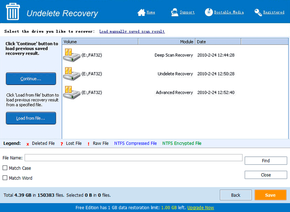
System Requirements for Power SMS 1.3 Release 3 serial key or number
- First, download the Power SMS 1.3 Release 3 serial key or number
-
You can download its setup from given links:

Power SMS 1.3 Release 3 serial key or number & Crack

Power SMS 1.3 Release 3 serial key or number& Kali Software Crack