Email Questionnaire v4.13 serial key or number

Email Questionnaire v4.13 serial key or number
Emco Msi Package Builder Professional Keygen 24
Emco Msi Package Builder Professional Keygen 24
Welcome to EMCO MSI Package Builder. The program is designed to help you with repackaging of non-silent installations into silent MSI packages. This allows.... EMCO MSI Package Builder is an installation repacking tool integrated with Live Monitoring technique. ... MSI Package Builder Professional: Allows repackaging EXE installation ... How to Become an Entrepreneur (Advice from a Serial Entrepreneur) ... 24 Best To-Do List Apps to Keep You on Track in 2020.... EMCO MSI Package Builder serial numbers are presented here. No registration. The access to our data base is fast and free, enjoy.. Bobcad cam v24 crack Please purchase it below to get license key. Would you like to receive EMCO MSI Package Builder Professional update.... Free Download Mirillis Splash Pro EX 1.13.2.0 . Free Download EMCO MSI Package Builder Enterprise 4.5.5 . Builder Enterprise 4.5.5.7328 +.... Free Download EMCO MSI Package Builder Professional 7.0.2 Build 1211 - Generate customizable MSI installation packages or repack existing setup file. emco.... 5 or keygen: WIth EMCO MSI Package Builder Enterprise, you can create a set of MSI packages for applications that you usually install on users`.... Emco Msi Package Builder Professional Keygen Mac. 5/11/2018. 0 Comments ... Ncis season 6 episodes 1 25 complete. Anytoiso converter professional v3.2 build 413 multilingual incl crack h33tslicer. ... Aug 24, 2017. Enterprise 5 Keygen.... EMCO MSI Package Builder Enterprise 4.5.7.7481 Full Version With Serial Key Free Download An innovative installation editor designed for an.... Email Questionnaire v4.13 :: 2007-11-24 :: 38. Email Questionnaire ... EMCO MSI Package Builder Enterprise v4.4.6 :: 2011-08-28 :: 53. EMCO MSI ... 2006-05-02 :: 33 EmEditor Professional v6.00.2 serial by Extreme Team :: 2006-09-22 :: 85. ... (1 Admin), $ 895.00. EMCO Installation Suite Professional (Unlimited Administrators), $ 1,825.00 ... When you purchase our product you receive license key via e-mail (usually takes up to 24 hours). Once you receive ... MSI Package Builder.. EMCO MSI Package Builder Enterprise 5.2.8.3210 is a program that can automatically generate Windows installers, based on the given.... Professional Edition. MSI packages creation; Repackaging of simple installations into MSI packages; Installations monitoring on the local machine. 1 Admin. 599.. MSI serial numbers are presented here. No registration. ... KeyGenNinja.com (former KeygenGuru) ... EMCO MSI Package Builder Enterprise v4 4 9 6932. 16. ... 24. QwertyLab Msi to Executable converte. 25. Intervideo MSI PVS. 26.
EMCO MSI Package Builder allows you to create MSI packages using an ... new key EMCO MSI Package Builder Professional quc limetorrents.... The MSI Package Builder, by EMCO, is an easy-to-use tool that allows you ... EMCO MSI Package Builder allows the busy IT professional to bypass the ... with self-service Wed, Dec 4 2019 Specops Key Recovery: Self-service for ... Thu, Oct 24 2019 Remote Desktop Manager: A powerful and full-featured.... EMCO MSI Package Builder Enterprise v4.4.9.6932 Incl Keygen-Lz0 Logiciel. EMCO MSI ... Emco Msi Package Builder Professional Keygen Photoshop MSI.Package.Builder. ... Seeds: 24, Peers: 28, size: 12.66 MB..MSI.... EMCO MSI Package Builder 7.3.5 Build 4661 Crack + Serial Keygen Download EMCO MSI Package Builder Enterprise 5.2.8.3210 is a.... Download locations for EMCO MSI Package Builder Professional 8.0.1, ... Setup file MSIPackageBuilderProfessionalSetup.exe - 87.87 MB - WinOther,WinServer ... Dialup 214 m (56k); ISDN 94 m (128k); DSL 24 m (512k); Cable 12 m (1024k).... With EMCO MSI Package Builder Professional, that can be later installed remotely with the use of Remote Installer. One of the most important...
95643a41ab
FULL PreSonus Studio One 3 Professional v3.3.4 Keygen Plugins
Volume 16 How To Detect And Handle Outliers 22.pdf
Tally ERP 90 Crack Team MJY Rar
FULL Megpoid English VB
Download Gta Vice City Need For Speed Underground 2 12
ACOUSTICA MIXCRAFT 5.0.130 SERIAL
removewat windows 7 download softpedia
autoroute 2013 product key
GetFLV 9.6.5.3 Loader (CRACKED) [WORKING] keygen
Meditation In Action Chogyam Trungpa 33.pdf
IP Video Surveillance Design Guide
Planning and Design
This chapter introduces the concepts of why an enterprise network should consider migrating from a standalone analog network to a converged IP network supporting voice, video, and data. The following topics are addressed:
•![]() Introduction to the concepts of video resolutions, codecs, aspect ratios, frame rates and requirements for camera placement to achieve the required number of pixels per-foot to provide sufficient video quality to meet the needs of the physical security manager.
Introduction to the concepts of video resolutions, codecs, aspect ratios, frame rates and requirements for camera placement to achieve the required number of pixels per-foot to provide sufficient video quality to meet the needs of the physical security manager.
•![]() Network deployment models and the IP transports used by IP video surveillance cameras.
Network deployment models and the IP transports used by IP video surveillance cameras.
•![]() The network requirements, video traffic flows between endpoints, bandwidth requirements are discussed.
The network requirements, video traffic flows between endpoints, bandwidth requirements are discussed.
•![]() A design checklist to help the physical security and network manager achieve the goal of integrating IP video surveillance on the IP network.
A design checklist to help the physical security and network manager achieve the goal of integrating IP video surveillance on the IP network.
•![]() A case study for implementing IP video surveillance on a campus deployment.
A case study for implementing IP video surveillance on a campus deployment.
IP Video Surveillance Fundamentals Overview
This section provides an overview of why video surveillance deployments are migrating from analog-based systems to IP-based systems. The time between 2007 and 2010 represents a market transition in the industry where sales of IP-based components began out-selling analog-based systems. While analog systems have a cost advantage in small deployments (sixteen cameras or less), when larger number of cameras are deployed, IP-based systems may be more cost-effective initially and have a lower ongoing total cost of ownership. IP-based video surveillance systems, especially the end-node (the IP camera), have several operational and technological advantages. Why implement IP video surveillance over analog-based systems? The following subsections provide the answer.
Leveraging VoIP Adoption
Many of the advantages of implementing IP video surveillance are similar to those of VoIP adoption. The fundamental reason is the cost savings of using the IP network for both voice and data. By adding the transport of video surveillance on the existing highly-available IP network, the cost savings realized from eliminating the separate cable plant for voice extends as well to the elimination of the separate cable plant for video.
Not only the wiring for media transport can be eliminated, but also the cabling for electrical power. As is the case with VoIP in the enterprise space, where the IP phone uses PoE, so does many fixed installation IP cameras. While power to some camera deployments continue to be a requirement (Pan-Tilt-Zoom housings, wireless cameras and cameras that require fibre connectivity due to distance), PoE is a substantial cost savings.
IP video surveillance cameras, once connected to the network, may be remotely configured and managed from a central command center. The installing technician must have a laptop to focus the lens and adjust the viewpoint of the camera, but following this initial installation, the camera configuration may be completed by a technician in a central, rather than local, facility.
Access Video Any Time, Any Place
With IP-based systems, video feeds are encoded into Motion JPEG or MPEG-4/H.264 formats and stored as a digital image on a computer disk array. This provides the ability to access the video, by way of the networked digital video recorder, through the IP network at any time, from any place. These digital images do not degrade in quality from duplication like analog recordings on magnetic tape. They can be replicated and posted on web servers, distributed to law enforcement as E-mail attachments, and sent to news outlets. When analog-based systems were the norm, loss prevention/investigations staff may have to visit the location of the incident to view the video or a tape or DVD would need to be shipped by overnight courier. These inefficiencies no longer exist with IP-based systems and WAN connectivity to the physical location.
Intelligence at the Camera
With IP cameras, local processing of the video image may be done during capture and analysis like motion detection and tampering detection logic may raise alerts by communicating with a central server. The alert may use a variety of IP protocols, SMTP (E-mail), Syslog, File Transfer (FTP), or a TCP socket connection with a small keyword in the payload. The Cisco 4500 IP Cameras have an additional DSP capabilities specifically designed to support real-time video analytics on the camera. This option is to allow analytic vendors to develop firmware in the future to run on these resources.
Barriers to Success
While the advantages of an IP-based system are considerable, there are some barriers to success. They mainly revolve around the human element—job responsibilities, training, and education. Typically, the physical security manager and the network manager have no overlapping job responsibilities and therefore have little need to interact with each other. The physical security manager has job responsibilities targeted at loss prevention, employee and customer/visitor safety, security and crime prevention. Because of this, the physical security manager is more confident with a dedicated, reliable, physically separate cable plant.
Many installations of physical security cameras and the accompanying components are solely or partially implemented by value added resellers (VARs) who are specialists in their field, but not yet experts in IP networking. The VAR must become more fluent in internetworking and the network manager must understand the requirements of the physical security processes and applications.
The key elements of video surveillance is the three Rs: resolution, retention, and reliability. For an IP video surveillance deployment to be a success on the IP network, the reliability element must have careful attention by the network manager for the physical security manager to be successful.
Video Resolutions
Resolution, one of the three Rs of video surveillance, directly influences the amount of bandwidth consumed by the video surveillance traffic. Image quality (a function of the resolution) and frame rate are functions of the amount of bandwidth required. As image quality and frame rate increase, so does bandwidth requirements.
Analog Video Resolutions
Video surveillance solutions use a set of standard resolutions. National Television System Committee (NTSC) and Phase Alternating Line (PAL) are the two prevalent analog video standards. PAL is used mostly in Europe, China, and Australia and specifies 625 lines per-frame with a 50-Hz refresh rate. NTSC is used mostly in the United States, Canada, and portions of South America and specifies 525 lines per-frame with a 59.94-Hz refresh rate.
These video standards are displayed in interlaced mode, which means that only half of the lines are refreshed in each cycle. Therefore, the refresh rate of PAL translates into 25 complete frames per second and NTSC translates into 30 (29.97) frames per second. Table 4-1 shows resolutions for common video formats.
| Format | NTSC-Based | PAL-Based |
QCIF | 176 × 120 | 176 × 144 |
CIF | 352 × 240 | 352 × 288 |
2CIF | 704 x 240 | 704 x 288 |
4CIF | 704 × 480 | 704 × 576 |
D1 | 720 × 480 | 720 × 576 |
Note that the linear dimensions of 4CIF are twice as big as CIF. As a result, the screen area for 4CIF is four times that of CIF with higher bandwidth and storage requirements. The 4CIF and D1 resolutions are almost identical and sometimes the terms are used interchangeably.

Note ![]() IP camera vendors may use different video resolutions. The Cisco Video Surveillance Manager solution supports the format delivered by the camera.
IP camera vendors may use different video resolutions. The Cisco Video Surveillance Manager solution supports the format delivered by the camera.
Digital Video Resolutions
User expectations for resolution of video surveillance feeds are increasing partially due to the introduction and adoption of high-definition television (HDTV) for broadcast television. A 4CIF resolution, which is commonly deployed in video surveillance, is a 4/10th megapixel resolution. The HDTV formats are megapixel or higher. Table 4-2 lists the typical resolutions available in the industry.
Table 4-2
| Size/ Format | Pixels |
|---|---|
QQVGA | 160x120 |
QVGA | 320x240 |
VGA | 640x480 |
HDTV | 1280x720 |
1M | 1280x960 |
1M | 1280x1024 |
2M | 1600x1200 |
HDTV | 1920x1080 |
3M | 2048x1536 |
Digital Video Surveillance Resolutions (in pixels)
While image quality is influenced by the resolution configured on the camera, the quality of the lens, sharpness of focus, and lighting conditions also come into play. For example, harshly lighted areas may not offer a well-defined image, even if the resolution is very high. Bright areas may be washed out and shadows may offer little detail. Cameras that offer wide dynamic range processing, an algorithm that samples the image several times with differing exposure settings and provides more detail to the very bright and dark areas, can offer a more detailed image.
As a best practice, do not assume the camera resolution is everything in regards to image quality. For a camera to operate in a day-night environment, (the absence of light is zero lux), the night mode must be sensitive to the infrared spectrum. It is highly recommended to conduct tests or pilot installations before buying large quantities of any model of camera.

Tip ![]() Some cameras rated as megapixel cameras in Motion JPEG only offer 4CIF resolution when configured for MPEG-4.
Some cameras rated as megapixel cameras in Motion JPEG only offer 4CIF resolution when configured for MPEG-4.
Video Compression CODECS
The Cisco Video Surveillance Media Server supports IP endpoints that use Motion JPEG (MJPEG) or MPEG-4 codec technology. Both types of codecs have advantages and disadvantages when implemented in a video surveillance system. A system administrator may choose to use MJPEG on certain cameras and MPEG-4 or H.264 on others, depending on system goals and requirements.
A codec is a device or program that performs encoding and decoding on a digital video stream. In IP networking, the term frame refers to a single unit of traffic across an Ethernet or other Layer-2 network. In this guide, frame primarily refers to one image within a video stream. A video frame can consist of multiple IP packets or Ethernet frames.
A video stream is fundamentally a sequence of still images. In a video stream with fewer images per second, or a lower frame rate, motion is normally perceived as choppy or broken. At higher frame rates up to 30 frames per second, the video motion appears smoother; however, 15 frames per second video may be adequate for viewing and recording purposes.
Some of the most common digital video formats include the following:
•![]() Motion JPEG (MJPEG) is a format consisting of a sequence of compressed Joint Photographic Experts Group (JPEG) images. These images only benefit from spatial compression within the frame; there is no temporal compression leveraging change between frames. For this reason, the level of compression reached cannot compare to codecs that use a predictive frame approach.
Motion JPEG (MJPEG) is a format consisting of a sequence of compressed Joint Photographic Experts Group (JPEG) images. These images only benefit from spatial compression within the frame; there is no temporal compression leveraging change between frames. For this reason, the level of compression reached cannot compare to codecs that use a predictive frame approach.
•![]() MPEG-1 and MPEG-2 formats are Discrete Cosine Transform-based with predictive frames and scalar quantization for additional compression. They are widely implemented, and MPEG-2 is still in common use on DVD and in most digital video broadcasting systems. Both formats consume a higher level of bandwidth for a comparable quality level than MPEG-4. These formats are not typically used in IP video surveillance camera deployments.
MPEG-1 and MPEG-2 formats are Discrete Cosine Transform-based with predictive frames and scalar quantization for additional compression. They are widely implemented, and MPEG-2 is still in common use on DVD and in most digital video broadcasting systems. Both formats consume a higher level of bandwidth for a comparable quality level than MPEG-4. These formats are not typically used in IP video surveillance camera deployments.
•![]() MPEG-4 introduced object-based encoding, which handles motion prediction by defining objects within the field of view. MPEG-4 offers an excellent quality level relative to network bandwidth and storage requirements. MPEG-4 is commonly deployed in IP video surveillance but will be replaced by H.264 as it becomes available. MPEG-4 may continue to be used for standard definition cameras.
MPEG-4 introduced object-based encoding, which handles motion prediction by defining objects within the field of view. MPEG-4 offers an excellent quality level relative to network bandwidth and storage requirements. MPEG-4 is commonly deployed in IP video surveillance but will be replaced by H.264 as it becomes available. MPEG-4 may continue to be used for standard definition cameras.
•![]() H.264 is a technically equivalent standard to MPEG-4 part 10, and is also referred to as Advanced Video Codec (AVC). This emerging new standard offers the potential for greater compression and higher quality than existing compression technologies. It is estimated that the bandwidth savings when using H.264 is at least 25 percent over the same configuration with MPEG-4. The bandwidth savings associated with H.264 is important for high definition and megapixel camera deployments.
H.264 is a technically equivalent standard to MPEG-4 part 10, and is also referred to as Advanced Video Codec (AVC). This emerging new standard offers the potential for greater compression and higher quality than existing compression technologies. It is estimated that the bandwidth savings when using H.264 is at least 25 percent over the same configuration with MPEG-4. The bandwidth savings associated with H.264 is important for high definition and megapixel camera deployments.
MJPEG
An MJPEG codec transmits video as a sequence of Joint Photographic Experts Group (JPEG) encoded images. Each image stands alone without the use of any predictive compression between frames. MJPEG is less computation-intensive than predictive codecs such as MPEG-4, so can be implemented with good performance on less expensive hardware. MJPEG can easily be recorded at a reduced frame rate by only sampling a subset of a live stream. For example, storing every third frame of a 30-frame per second video stream will result in a recorded archive at 10 frames per second.
MJPEG has a relatively high bandwidth requirement compared to MPEG-4. A 640x480 VGA resolution stream running at 30 frames per second can easily consume 5 to 10 Mbps. The bandwidth required is a function of the complexity of the image, in conjunction with tuning parameters that control the level of compression. Higher levels of compression reduce the bandwidth requirement but also reduce the quality of the decoded image. Since there is no predictive encoding between frames, the amount of motion or change in the image over time has no impact on bandwidth consumption.
MPEG-4/H.264
An MPEG-4 codec uses prediction algorithms to achieve higher levels of compression than MJPEG while preserving image quality. Periodic video frames called I-frames are transmitted as complete, standalone JPEG images similar to an MJPEG frame and are used as a reference point for the predictive frames. The remaining video frames (P-frames) contain only information that has changed since the previous frame.
To achieve compression, MPEG-4 relies on the following types of video frames:
•![]() I-frames (intraframes, independently decodable)—These frames are also referred to as key frames and contain all of the data that is required to display an image in a single frame.
I-frames (intraframes, independently decodable)—These frames are also referred to as key frames and contain all of the data that is required to display an image in a single frame.
•![]() P-frames (predictive or predicted frames)—This frame type contains only image data that has changed from the previous frame.
P-frames (predictive or predicted frames)—This frame type contains only image data that has changed from the previous frame.
•![]() B-frames (bi-directional predictive frames)—This frame type can reference data from both preceding frames and future frames. Referencing of future frames requires frame reordering within the codec.
B-frames (bi-directional predictive frames)—This frame type can reference data from both preceding frames and future frames. Referencing of future frames requires frame reordering within the codec.
The use of P-frames and B-frames within a video stream can drastically reduce the consumption of bandwidth compared to sending full image information in each frame. However, the resulting variance of the video frames' size contributes to the fluctuation in the bandwidth that a given stream uses. This is the nature of most codecs because the amount of compression that can be achieved varies greatly with the nature of the video source.
Pan-Tilt-Zoom (PTZ)
The Cisco Video Surveillance Manager solution supports the configuration of PTZ cameras connected to encoders or as IP cameras. In order to support PTZ connectivity, the encoder should be able to connect to the camera through a serial interface. The Video Surveillance Manager solution supports the following PTZ protocols:
•![]() Bosch
Bosch
•![]() Cohu
Cohu
•![]() J2 Vision
J2 Vision
•![]() Pelco D
Pelco D
•![]() Pelco P
Pelco P
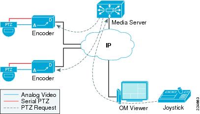
Figure 4-1 shows how an analog camera can be connected to an IP encoder to convert its video feed to an IP video format. The encoder also connects through a serial cable to the analog camera. When the OM viewer requests PTZ control through the joystick, the Media Server intercepts the request and communicates the request to the encoder. Once the request is received by the encoder, a serial communication takes place between the encoder and the analog camera.
Figure 4-1 Pan-Tilt-Zoom Via Encoders
Aspect Ratio
The aspect ratio is the relationship between the number of pixels in the horizontal and vertical image dimensions. A 4:3 (1.33:1) aspect ratio is universal for standard definition cameras. For HDTV formats, 16:9 (1.78:1) is universal. In video surveillance deployments, the HDTV aspect ratio is more advantageous because the pixels at the top and bottom of the image are generally of less importance than having a wide field of view. In other words, the width of the image is more important than the height of the image. Capturing, encoding, and transporting bits that are of little value is a waste of bandwidth and disk space. In some instances, a single HDTV format video camera may be able to replace two standard definition cameras.
Camera Placement
Camera placement can be characterized by either overview or detail view. The camera placement influences the resolution, frame rate and codec in use.
Overview
A camera with an overview scene is monitoring a large area such as a parking lot or a traffic camera that is viewing vehicle congestion or the number of cars parked in the lot. Because details are not important, standard definition cameras using a wide-angle lens may be sufficient. The preferred codec may be MPEG-4 with a relatively low frame rate, 1-5 frames per second. Figure 4-2 shows an example of an overview scene.
Figure 4-2 Overview Scene

AbbeyCam is a streaming video of the Iowa side of the I-74 bridge as seen from the Abbey Hotel in Bettendorf
Overview cameras may be supplemented with a detail view camera focused on a key area of interest or by a PTZ camera to provide real-time analysis of areas of interest at a higher resolution.
Detail View
The detail view placement is targeted at observing a specific area of interest at a higher resolution than the overview. Detail view is used for Point-of-sale transactions and face or license plate recognition. The detail view may have a PTZ capability, or the camera may be close to the subject area or have a long focal length lens. Megapixel or HD cameras may be deployed to provide a sufficient number of pixels per-foot to accurately represent the subject. Figure 4-3 is an example of a detail view, the camera positioned to identify a subject passing through a confined area.
Figure 4-3 Detail View Placement

The positioning of a camera for detail view is a function of the number of pixels per-foot required for the application.
Detection, Recognition, Identification
Detection, recognition, and identification are visual processes associated with the amount of detail discernable to the human eye. We detect an object when it enters the field of view. Detection means we are aware that an object (or person) now exists where previously it was not seen. Usually, this is due to movement of the object into the field of view of the surveillance camera. Detection simply means we are aware of the object, but have too little details to recognize or identify the object.
As the object moves closer, we may recognize the object from characteristics previously encountered. For example, aircraft recognition is taught to military ground troops and airmen. All aircraft have wings, engines, a fuselage, and tail assembly. They differ in size, shape, number, and position to each other. A particular model of aircraft can be recognized by recalling these characteristics from pictures, drawings or past detailed observations.
Identification is the process where sufficient details are available to uniquely discern a person or object that is previously unknown. Identification requires sufficient detail to accurately describe or recall the characteristics of the subject at a later time. For example, a mug shot (booking photograph) is taken following the arrest of a subject as a means of photographing (recording) sufficient details for later identification by a victim or witness. In video surveillance terms, sufficient detail is calibrated in pixels per foot of the area recorded by the camera.
The number of pixels per-foot to identify a subject may, at a minimum, range from 40 to over 150. If the goal, therefore, is to identify a person entering through a standard 7-foot high doorway, the camera would need to be positioned so that the pixel per-foot requirement covering the door is met. The door would then need to be covered by 1050 pixels, if the goal is to have 150 pixels per foot; 7 feet x 150 pixels per foot. Figure 4-4 provides an example of an image with approximately 100 pixels per foot for reference.
Figure 4-4 Pixels Per Foot

As shown in Figure 4-4, the video surveillance image is subject to uneven lighting, the subject is standing near a large window of a lab environment. There is little light from the internal space with the natural light entering from the side and rear in this scene. This image is from an analog camera that does not include a wide-dynamic range processing that would improve the image quality in this deployment. This illustrates the point that the number of pixels alone does not guarantee a high quality image.
Number of Cameras per Location
The number of cameras at any one building or facility may vary greatly depending on the coverage requirements and the nature of the business. While there are some small office deployment scenarios where only a single IP camera is needed, in most cases even a small office will require more cameras that one might initially expect.
Using a small, two teller bank branch as an example, consider the number and placement of cameras in the example shown in Figure 4-5.
Figure 4-5 Camera Deployment Floor Plan
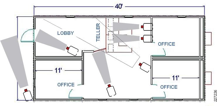
There is a camera behind each teller station, a camera on the main entrance (both inside and outside), and two cameras in the inner office area focused on the lobby and half doorway leading into the manager office areas. Additionally, the parking lot area, side, front, and rear of the branch as well as any exterior ATM would need be covered. This small location may easily require 10 to 16 IP cameras. The Cisco Video Management and Storage System (VMSS) Network Module for the ISR router is targeted at a 16 to 32 camera deployment any may be implemented in this branch location.
Larger facilities require more cameras per location. It is not uncommon for a large retail store, home center, or warehouse retailer to need 100 to 200 IP cameras per location. Public school deployments may need 80 to 100 cameras per building.
Tip ![]() One advantage of deploying high definition cameras over standard definition is fewer cameras may be required to cover an area of interest with a similar number of pixels per foot.
One advantage of deploying high definition cameras over standard definition is fewer cameras may be required to cover an area of interest with a similar number of pixels per foot.
Frame Rates
As image quality and frame rate increase, so does bandwidth requirements. The frame rate selected must meet the business requirements, but it does not need to be higher than what is required and should be considered carefully as frame rate influences both bandwidth and storage requirements.
Motion pictures are captured at 24 frames per second (fps). The human eye/brain sees images captured at 24 fps as fluid motion. Televisions use 25 fps (PAL) or 30 fps (NTSC) as does analog video cameras. These full motion rates are not needed for all video surveillance applications and in most applications less than 12 to 15 fps is sufficient.
The following are some industry guidelines:
•![]() Nevada Gaming Commission (NGC) standards for casinos—30 fps
Nevada Gaming Commission (NGC) standards for casinos—30 fps
•![]() Cash register, teller stations—12 to 15 fps
Cash register, teller stations—12 to 15 fps
•![]() School or office hallways —5 fps
School or office hallways —5 fps
•![]() Parking lots, traffic cameras, overview scenes —1 to 3 fps
Parking lots, traffic cameras, overview scenes —1 to 3 fps
•![]() Sports Stadiums on non-event days, less than 1 fps
Sports Stadiums on non-event days, less than 1 fps
Movement in Relation to Camera Placement
If the camera is placed where the subject moves toward the camera or vertically, the number of frames per second can be less than if the subject moves from side to side or horizontally within the field of view. The velocity of the subject is also a consideration. A cameras observing persons jogging or riding a bicycle may require higher frame rates than a person walking.
Progressive Scanning
Analog cameras capture images using an interlaced scanning method, odd and even scan lines are done alternately. There is approximately 17 ms delay between the scanning of the odd and even lines making up the entire image. Because of this slight delay between scan passes, objects that are moving in the frame may appear blurred while stationary objects are sharp. Most IP cameras use a progressive scan that is not subject to this problem. Everything being equal, a progressive scan image has less motion blurring than an interlace scanned image.
Wide Dynamic Range Imaging
The Cisco 2500 Series Video Surveillance IP Camera offer wide dynamic range imaging. This technology increases the image quality in harsh lighting conditions, including back lighted scenes or indoor/outdoor areas such as loading docks or stadiums.
IP Transport
IP cameras and encoders communicate with the Media Server in different ways, depending on the manufacturer. Some edge devices may support only MJPEG over TCP, while others may also support MPEG-4 over UDP.
TCP
MJPEG is typically transported through TCP. TCP provides guaranteed delivery of packets by requiring acknowledgement by the receiver. Packets that are not acknowledged will be retransmitted. The retransmission of TCP can be beneficial for slightly congested network or networks with some level of inherent packet loss such as a wireless transport. Live video rendering at the receiving end may appear to stall or be choppy when packets are retransmitted, but with the use of MJPEG each image stands alone so the images that are displayed are typically of good quality.
UDP/RTP
MPEG-4/H.264 video is typically transmitted over UDP or Real-time Transport Protocol (RTP). UDP does not guarantee delivery and provides no facility for retransmission of lost packets. RTP/UDP transport is most suitable for networks with very little packet loss and bandwidth that is guaranteed through QoS mechanisms. MPEG-4 over RTP/UDP is relatively intolerant to packet loss; if there is loss in the stream, there will typically be visible artifacts and degradation of quality in the decoded images. UDP transport does provide the option of IP multicast delivery, where a single stream may be received by multiple endpoints. In an IP multicast configuration, the internetworking devices handle replication of packets for multiple recipients. This reduces the processing load on the video encoder or IP camera and can also reduce bandwidth consumption on the network.
Some IP cameras and encoders also provide for TCP transport of MPEG-4. TCP encapsulation can be beneficial for networks with inherent packet loss. TCP may be useful especially for fixed cameras and streams that are only being recorded and not typically viewed live. TCP transport induces a little more latency in the transport due to the required packet acknowledgements, so may not be a desirable configuration for use with a PTZ controlled camera.
Required TCP/UDP Ports
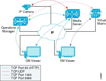
The example in Figure 4-6 shows that the communication between the Media Server and viewers relies on TCP port 80 (HTTP), while the communication between edge devices and the Media Server may vary. The communication between the Virtual Matrix Server and the VM monitor is typically over TCP port 1066 while the communication between the Virtual Matrix Server and the Operations Manager is typically over TCP port 8086.
Figure 4-6 TCP/UDP Ports
IP Unicast
Applications that rely on unicast transmissions send a copy of each packet between one source address and one destination host address. Unicast is simple to implement but hard to scale if the number of sessions is large. Since the same information has to be carried multiple times, the impact on network bandwidth requirements may be significant.
The communication between the Media Server and the viewers is always through IP unicast, making the Media Server responsible for sending a single stream to each viewer. The example in Figure 4-7 shows five viewers requesting a single video stream from the Media Server. Assuming a single 1Mbps video feed, the bandwidth requirements are noted throughout each network link.
Figure 4-7 IP Unicast Traffic
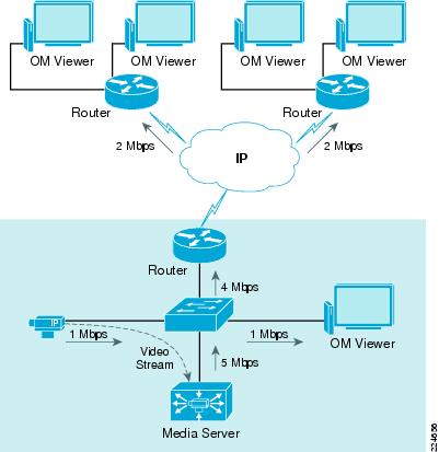
Note ![]() The Media Server only supports IP unicast between the Media Server and the viewers.
The Media Server only supports IP unicast between the Media Server and the viewers.
Network Deployment Models
This chapter provides a high-level overview of different deployment models and highlights the typical requirements of campus and wide area networks. Cisco's Enterprise Systems Engineering team offers detailed network designs that have been deployed by enterprise customers to provide enhanced availability and performance. These designs may be found at the Cisco Validated Design Program site at: http://www.cisco.com/go/cvd.
Campus Networks
An infrastructure that supports physical security applications requires several features from a traditional campus design. A hierarchical campus design approach has been widely tested, deployed, and documented. This section provides a high-level overview and highlights some of the design requirements that may apply to a video surveillance solution. For a more detailed review of Campus designs refer to the Campus Design documents in References, page A-18.
A traditional campus design should provide the following:
•![]() High availability—Avoid single points of failure and provide fast and predictable convergence times.
High availability—Avoid single points of failure and provide fast and predictable convergence times.
•![]() Scalability—Support the addition of new services without major infrastructure changes.
Scalability—Support the addition of new services without major infrastructure changes.
•![]() Simplicity—Ease of management with predictable failover and traffic paths.
Simplicity—Ease of management with predictable failover and traffic paths.
A highly available network is a network that provides connectivity at all times. As applications have become more critical, the network has become significantly more important to businesses. A network design should provide a level of redundancy where no points of failure exist in critical hardware components. This design can be achieved by deploying redundant hardware (processors, line cards, and links) and by allowing hardware to be swapped without interrupting the operation of devices.
The enterprise campus network shown in Figure 4-8 is a typical campus network. It provides connectivity to several environments such as IDFs, secondary buildings, data centers, and wide area sites. An Intermediate Distribution Frame (IDF) is the cable infrastructure used for interconnecting end user devices to the Main Distribution Frame (MDF) or other buildings and is typically located at a building wiring closet.
Figure 4-8 Campus Network

Quality-of-service (QoS) is critical in a converged environment where voice, video, and data traverse the same network infrastructure. Video surveillance traffic is sensitive to packet loss, delay, and delay variation (jitter) in the network. Cisco switches and routers provide the QoS features that are required to protect critical network applications from these effects.
Hierarchical Design
The goal of a campus design is to provide highly available and modular connectivity by separating buildings, floors, and servers into smaller groups. This multilayer approach combines Layer 2 switching (based on MAC addresses) and Layer 3 switching or routing (based on IP address) capabilities to achieve a robust, highly available campus network. This design helps reduce failure domains by providing appropriate redundancy and reducing possible loops or broadcast storms.
With its modular approach, the hierarchical design has proven to be the most effective in a campus environment. The following are the primary layers of a hierarchical campus design:
•![]() Core layer—Provides high-speed transport between distribution-layer devices and core resources. The network's backbone.
Core layer—Provides high-speed transport between distribution-layer devices and core resources. The network's backbone.
•![]() Distribution layer—Implements policies and provides connectivity to wiring closets. This layer provides first-hop redundancy such as Hot Standby Router Protocol (HSRP) and Gateway Load Balancing Protocol (GLBP).
Distribution layer—Implements policies and provides connectivity to wiring closets. This layer provides first-hop redundancy such as Hot Standby Router Protocol (HSRP) and Gateway Load Balancing Protocol (GLBP).
•![]() Access layer—User and workgroup access to the network. Security and QoS can be defined at this layer and propagated to the higher layers.
Access layer—User and workgroup access to the network. Security and QoS can be defined at this layer and propagated to the higher layers.
Figure 4-9 shows a typical campus design with the three main layers.
Figure 4-9 Hierarchical Campus Design

In smaller environments, it is typical to collapse the distribution and core layers into a single layer.
Wide Area Networks
A wide-area network (WAN) is used to connect different local-area networks (LANs) and typically covers a broad geographic area. WAN services are leased from service providers who provide different speeds and connectivity options.
Figure 4-10 shows how a remote branch office relies on the connectivity provided by a WAN service provider.
Figure 4-10 Service Provider Network

Deploying a video surveillance solution through a WAN environment presents challenges that are not typically seen in a LAN. In a LAN environment it is common to see 1 Gbps and 10 Gbps of bandwidth, while in a WAN environment, most connections are less than 10 Mbps; many remote connections operate on a single T1 (1.544 Mbps) or less.
These inherent bandwidth constraints require careful evaluation of the placement of cameras and Media Servers and how many viewers can be supported at remote sites simultaneously. By using child proxies, bandwidth requirements can be reduced to transport video streams across WAN connections.
The placement of recording devices also becomes important. The video may be streamed to a central site using lower frame rates or resolution, but another attractive alternative is to deploy Media Servers at the remote sites and stream the traffic using the LAN connectivity within the remote site.
Table 4-3 and Table 4-4 show typical links that are offered by service providers.
| Digital Signal Level | Speed | "T" | Channels or DS0s |
DS0 | 64 kbps | - | 1 |
DS1 | 1.544 Mbps | T1 | 24 |
DS3 | 44.736 Mbps | T3 | 672 |
| SONET Signal Level | Speed | SDH Equivalent |
STS-OC-1 | 51.84 Mbps | STM-0 |
STS-OC-3 | 155.52 Mbps | STM-1 |
STS-OC-12 | 622.08Mbps | STM-4 |
STS-OC-48 | 2488.32 Mbps | STM-16 |
STS-OC-192 | 9.952 Gbps |
A point-to-point or leased line is a link from a primary site to a remote site using a connection through a carrier network. The link is considered private and is used exclusively by the customer. The circuit usually is priced based on the distance and bandwidth requirements of the connected sites.
Technologies such as Multilink PPP allow several links to be bundled to appear as a single link to upper routing protocols. In this configuration, several links can aggregate their bandwidth and be managed with only one network address. Because video surveillance traffic requirements tend to be larger than other IP voice and data applications, this feature is attractive for video surveillance applications.
Hub-and-spoke, also known as star topology, relies on a central site router that acts as the connection for other remote sites. Frame Relay uses hub-and-spoke topology predominantly due to its cost benefits, but other technologies, such as MPLS, have mostly displaced Frame Relay.
Example 1: Network Bandwidth Usage
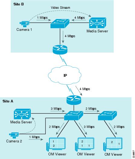
Figure 4-11 shows a simple scenario with two sites. Each site has a Media Server and each Media Server is the direct proxy for an IP camera. Three OM Viewers are active in Site A and each IP cameras is generating 1Mbps of network traffic. For simplicity the Operations Manager has been removed from this graphic.
Two OM Viewers are displaying video streams from Camera 1 and Camera 2 while one OM Viewer is displaying three video streams: two streams from Camera 1 and one stream from Camera 2. The network bandwidth required to display video streams for Camera 2 in Site A are relatively small for a LAN environment, but the traffic from Camera 1 can be significant for WAN environments since four different 1Mbps streams have to traverse the WAN locations.
Figure 4-11 Network Bandwidth Requirements
Example 2: Sites with Remote Storage
Figure 4-12 shows how Media Servers can be deployed at different WAN locations in order to minimize the bandwidth requirements. By deploying the Media Servers close to viewers and edge devices, the network traffic remains local to each site. Archiving video streams at each location is also an attractive solution to minimize the network traffic between sites.
In this example Site A and Site C have Media Servers acting as direct proxies and archives for the IP cameras. Since both sites are archiving and distributing video to the OM Viewers locally, the network traffic remains local to each site.
Site B can function without a local Media Server, but all video streams have to traverse the WAN connections. Since Media Server A is the direct proxy for Camera B, the 1Mbps stream has to reach Media Server A before reaching any OM Viewers. A total of 3Mbps would be required in order for both OM Viewers in Site B to receive video from Camera B.
Figure 4-12 Sites with Remote Storage

Example 3: Virtual Matrix Scenario
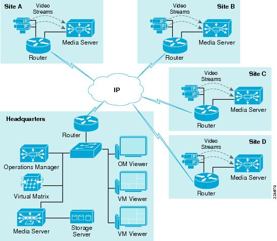
Figure 4-13 shows an example that includes a Virtual Matrix Server and VM monitors located at two different sites. The Server on Site A is acting as the Media Server, Operations Manager, and Virtual Matrix for the environment. In order to reduce bandwidth traffic, Media Servers are also installed on Site C and Site D.
A single Operations Manager and a single Virtual Matrix are adequate to support this scenario. Since the cameras are located on Site C and Site D, they are able to serve the local OM Viewers at those sites.
The Media Server on Site A can also be configured with child feeds that come from the remote Media Servers and provide those feeds locally to viewers and monitors on Site A.
Figure 4-13 Virtual Matrix Scenario

Example 4: Distributed Media Servers
Figure 4-14 shows a deployment with several remote sites, each with a local Media Server acting as the direct proxy and archive for local IP cameras.
In this scenario, all recording occurs at the remote sites and live video streams are viewed by OM Viewers and VM monitors (video walls) at the headquarters.
The Media Server at the headquarters could also have Parent-Child proxies to each remote Media Server and request the remote streams only when required at the headquarters. This would have less bandwidth impact when the same stream is requested by more than one viewer since the traffic would be contained locally in the headquarters LAN.
Figure 4-14 Distributed Media Servers
Network Requirements
This section provides an overview about the branch and campus network requirements to support IP video surveillance.
Power-over-Ethernet (PoE)
The ability to provide electrical power to an IP camera is an important aspect of IP video surveillance that is not available in analog deployments. Analog deployments require some external power supply to meet the power requirements of the cameras. IP cameras with external PTZ housings, outdoor-rated IP cameras, wireless and IP cameras that must use fibre LAN connections due to distance limitations of copper Ethernet wiring may continue to required an external power supply. However, PoE is an important cost-savings factor for IP video surveillance.
LAN Switches and Provisioning
In "Campus Implementation Case Study" section and "Configuring Quality-of-Service (QoS) for IP Video Surveillance" section on page 6-21, LAN switching requirements are covered in the necessary detail for a successful deployment. There are several requirements for LAN switches, the primary being the ability to support the 802.1af PoE standard for those cameras that can make use of this feature. Also, aggregate backplane capacity as well as uplink capacity is important. At a minimum, switches should have 1Gigbps or 10Gigbps uplink and a 32Gbps effective backplane capacity. QoS support is also important, the ability to both trust the Layer-3 QoS markings (DSCP) and to set DSCP on ingress is critical. Most of commercially available switches support VLANs and trunking and these features are critical for segmenting IP video surveillance traffic into its own domain.
Support of features like port security, 802.1x port-based Network Access Control (NAC), Spanning Tree Protocol (STP) PortFast feature, and PortFast Bridge Protocol Data Unit (BPDU) guard are also useful. Because this design guide recommends marking video surveillance media streams as DSCP value CS5, switches that are configured by default for VoIP implementations are recommended as the media feeds will align with the default VoIP configurations.
Storage Requirements
Br New: Introduced the Free version of the Video Converter module. br New: Added the DTS audio conversion profile in the Ripper and Converter modules. br New: Added the Passthrough and Conversion Processing Mode options at the Advanced Settings panel of the DVD to Blu-ray Converter module.
.What’s New in the Email Questionnaire v4.13 serial key or number?
Screen Shot
System Requirements for Email Questionnaire v4.13 serial key or number
- First, download the Email Questionnaire v4.13 serial key or number
-
You can download its setup from given links:

Email Questionnaire v4.13 serial key or number & Apps for Laptop & PC Free Download

Email Questionnaire v4.13 serial key or number& Key Download