NI LabVIEW Sound and Vibration Toolkit v4.0 serial key or number

NI LabVIEW Sound and Vibration Toolkit v4.0 serial key or number
【国内正規モデル】!真言宗 数珠 数珠 本式数珠 男性用 尺二 琥珀 2色梵天房 本式数珠 数珠袋付き ·現品お届け 2色梵天房!·【格安販売中】!!
最初は海へ入り、一通りのルアーをキャスト。
この場所では機会があればシンペンを投げまくっていますが全くうんともすんともな場所。もう少し沖に行ける時期になれば小さなスプーンでクロヒラアジは何度かhit したことがあるのでシンペンでもhit するはずと思っているんですけどね・・。
潮が満ちてきたので岸まで戻りそこからは打ち込み的な釣りへ変更。夕マズメの海へ大遠投します。
・・そして何の魚信も無いまま日没。
日没から10 分後、まだ薄明るい時間帯に突如激しいアタリ。
感じとしては50cm ぐらいのタマンか。
しかしhitには至らずでそこからタマンっぽいアタリは途絶えました。
そしてそれから30 分後、ちょうど満潮の時間帯に・・
ゴン・・ゴン・・
【国内正規モデル】!真言宗 数珠 数珠 本式数珠 男性用 尺二 琥珀 2色梵天房 本式数珠 数珠袋付き ·現品お届け 2色梵天房!·【格安販売中】!!
ホーム > 冠婚葬祭、宗教用品 > 【国内正規モデル】!真言宗 数珠 数珠 本式数珠 男性用 尺二 琥珀 2色梵天房 本式数珠 数珠袋付き ·現品お届け 2色梵天房!·【格安販売中】!!
と何やら大物が食っている感触。
しばらく待っていると・・
ググーッ!っとロッドが入ったので合わせる!
ギィィ・・・
多少ドラグも出る良い引き。
・・しかし乗ったかと思っていたのですが応戦していると途中で軽くなってしまった・・
うわー・・かかってなかった・・。
針の手前までの部分をくわえたまま引っ張っていたようで、針がかからずだったようです。
再度、大遠投それから再度大遠投し、しばらく探っていると・・
ゴン・・ゴン・・
・・また来た・・!さっきのやつか・・
グイッ・・グイッ・・
・・入りそう・・
【国内正規モデル】!真言宗 数珠 数珠 本式数珠 男性用 尺二 琥珀 2色梵天房 本式数珠 数珠袋付き ·現品お届け 2色梵天房!·【格安販売中】!!
・・ググーンッ!!また食ってきてロッドが入ったのでフッキング!
ドスンと入り、今度は遂に来た。
ギギギィ・・・
ドラグはフルロックに近く設定しており、ギューっとロッドが絞めこまれてブチ曲がっていく。
思ってたより大物・・!
ギギィィー・・
・・しかし様子がおかしい・・
折れんばかりにロッドがかなり締め込まれて
ギギギィィーー
・・とドラグが出る。
うおお・・なんだか想定外のすごいパワー・・!
・・ヤバイ・・この感じは切れるかも・・汗
ゆっくりと締めこまれていくためキツめに締めたドラグがスムーズに出てくれない・・!
ロッドはしっかり立てているにも関わらずラインが切れてしまうのではという締め込まれ方に危険を感じてドラグを一気に6 ~7 割くらいまで緩めると・・
ギィィィーーーーーーーーーーーーーーーーーーーーーーーーーーーーーーーーーーーーーーーーーーーーーーーーーーーーーーーーーーーーーーーーーーーーーーーーーーーーーーーーー!!!!!
ものすごい勢いでドラグが出て止まらない。
・・ヤバイ・・汗
pe3 号が190m 巻けるリールに下糸40m くらいとファイヤーラインの3 号を150m 巻いているので実質走らせていいのは150m 先まで。
大遠投した先から走られているので、相手はすでにけっこう沖に居る・・。
動きを止めようとドラグを8 割ぐらいまでしめるも・・
【国内正規モデル】!真言宗 数珠 数珠 本式数珠 男性用 尺二 琥珀 2色梵天房 本式数珠 数珠袋付き ·現品お届け 2色梵天房!·【格安販売中】!!
ギィィィーーーーーーーーーーーーーーーーーーーーーーーーーーーーーーーーーーーーーーーーーーーーーーーーーーーーーーーーーーーーーーーーーーーーーーーーーーーーーーーーー!!!!!
相手も疲れてくるだろうと予想して対応していたのですが、疲れてくる様子は微塵もない・・
(※ちなみにこのときはまだタマンだと思っています)
【国内正規モデル】!真言宗 数珠 数珠 本式数珠 男性用 尺二 琥珀 2色梵天房 本式数珠 数珠袋付き ·現品お届け 2色梵天房!·【格安販売中】!!
【国内正規モデル】!真言宗 数珠 数珠 本式数珠 男性用 尺二 琥珀 2色梵天房 本式数珠 数珠袋付き ·現品お届け 2色梵天房!·【格安販売中】!!
ファイヤーラインは無くなる寸前・・。
一か八かフルロックで止めなきゃヤバイ・・!
満を持して9~9.5
割のほぼほぼフルロック状態にする!・・するとほんの一瞬だけ動きが遅くなったが相手がさらに本気を出した・・!!
ギィィィーーーーーーーーーーーーーーーーーーーーーーーーーーーーーーーーーーーーーーーーーーーーーーーーーーーーーーーーーーーーーーーーーーーーーーーーーーーーーーーーー!!!!!
・・このときようやく相手がタマンじゃないことに気がつく(^^;
がしかし遅かった・・。
体ごと持っていかれそうになるのでコンクリートの塀に体をあずけ、ロッドを両手で抱きかかえるようにフルパワーで持ち、耐える!!
うおおお!
ギィィィーーーーーーーーーーーーーーーーーーーーーーーーーーーーーーーーーーーーーーーーーーーーーーーーーーーーーーーーーーーーーーーーーーーーーーーーーーーーーーーー!!!!!
しかし相手はこのフルロックに近い状態でも平然と走り続ける・・。
見た感じ止まる気が全くしない・・。
見上げるとロッドの状況はまさしくyoutube の離島の映像でgt に走られている時の様子と一緒・・・!
・・これはgtだ・・。。
うおぉぉぉ・・!
ファイヤーラインがもう無くなる・・!!
ッバーーンッ!!!!
という激しい音と衝撃。
・・うわぁロッドが折れた・・。
と思うほどの衝撃と感触でしたが確かめてみるとロッドは無事。
・・下糸が切れていました。
めちゃめちゃ曲がっていたロッドが一気に戻った衝撃だったんですね。
うわーーー・・・
・・・・・・・・。。
口が開いたままでその場に10 分間ほど放心状態・・
今まで生きてきて、これほどの衝撃体験はしたことがない。
タマンならもっと簡単に止めきれる・・。
これは15〜20kg ぐらいのロウニンアジだったのでは?と思っています・・。
(翌日ある方に聞いたところ、やはり20kg〜30kgのロウニンアジが回遊してくる場所らしい)
最初にドラグを緩めてしまい沖を向かせて一気に走らせてしまったこともありますが、今回の最大の敗因はラインを150m しか巻いていないことだと感じました・・。
(ウェーディング用に使っているクラスのリールなのでラインが太くなる程に糸巻き量が減る・・)
根ズレなどはそれほど心配無い場所でしたので、ラインにもっと余裕があれば一旦止まるまで耐えることは出来たかもしれません。
そうすれば回収しては出されを繰り返しながらも獲れた可能性は0では無かったのではないかという感触がありました。
ロッドも安価ながらもオオニベ(20kg ~30kg にもなる)対応可能なロッドなので全く獲れない感触でもなかったのです。
あと、自分で折れを修理したこのロッドはこれほどのパワーと衝撃にさらされても全然大丈夫なことにはちょっと驚きでした。
折れ修理の強度は全く問題ないですね。
ロウニンアジの魅力を知る今後はgt狙いに変更しようかと本当に思ってしまうほど衝撃が大きかったですが、また新たなタックルをそろえたりし始める資金が無いのでとりあえずは今まで通りタマンメインでの釣りをやっていこうと思っていますが・・
しかしgtとまた勝負してみたいですね。
タマンを狙っている以上、また遭遇することがあると思います。
前回gtを目撃した場所はまた別の場所なのですが、実は一昨年その場所でもgtだったかもしれないやつが全く止まらなくてあっさり切られていますので・・!
その時の記事はこちら

それではまたgtに遭遇したら書きたいと思います!
====================
□ プライヤー
・ umibozu フィッシングプライヤー
詳細: https://amzn.to/2juktfi
====================
amazonアウトレット
 さまざまな商品がアウトレット価格
 アマゾンアウトレットにはいろんな商品があります!
・釣具・ アウトドア ・ バッグ・パソコン&周辺機器・食品・お米・家電
amazonアウトレットについては過去記事参照!amazonアウトレットは本当にお得?amazonアウトレットで実際に購入!
amazonアウトレット商品は、amazon配送センターの商品が対象ですのでプライム会員は送料無料!アマゾンプライムとは?
FREE License Activator for National Instruments - LabVIEW Module & Toolkit 2017
FREE License Activator for National Instruments - LabVIEW Module & Toolkit 2017

Module & Toolkit 2017:
-LabVIEW Advanced Signal Processing Toolkit 2017
-LabVIEW Database Connectivity Toolkit 2017
-LabVIEW Desktop Execution Trace Toolkit 2017
-LabVIEW Digital Filter Design Toolkit 2017
-LabVIEW DCS Module 2017 (2017DCS)
-LabVIEW 2017 Compile Farm 2017
-LabVIEW 2017 FPGA Module (English)
-LabVIEW MathScript RT Module 2017
-LabVIEW Robotics Module 2017
-LabVIEW Statechart Module 2017
-LabVIEW VI Analyzer Toolkit 2017
-LabVIEW Unit Test Framework Toolkit 2017
-Automatic Verification Platform for Safety-Critical FPGA
-BSR Observer 1.0.0
-BSR Quality 1.0.0
-CANalytics 1.0.0
-DAQ-Logger 1.3.0
-easyDatalogger standalone 4.6.1.585
-EtherCAT Library for LabVIEW 2.9.5
-HaroUT 1.0.2 Runtime Engine
-iDaq 4.0.0.1623
-iTestSystem (iTS) 2014 with Drivers
-LabVIEW Control Design and Simulation Module 2017
-MGI Solution Explorer 2.0.0.47
-NI Sound and Vibration 2017
-NI TestStand 2016 SP1
-Oscilloscope 4.3.0.185
-SeeSV-Postprocess 1.7.0
-SeeSV-S205 1.7.0
-Sentinel LDK AddOn 3.0
-TestView Integrator 2016 r12
-NI Vision Development Module 2017
-LabVIEW 2017 Real-time Module English
-DFTK-2017
-DIAdem 2017 English
-SoftMotion Module 2017
-Example Code for Production Test Systems
-F2F Sample
-LabVIEW Evaluation for Embedded Applications
-Measure Physical Systems with Sensors or Actuators
-LabVIEW NXG
-LabVIEW Sound Board
-Example Code of Verification and Validation

Download here:
NI License Activator 1.1
NI License Activator 1.2
NOTE:
-Run installer
-For serial Run "NI License Activator 1.2.exe" and from "Option" click on "Generate Serial Number"
-Install Update
-After install run "NI License Activator 1.2.exe" and click "Activate" for any modules
Blog.Teknisi
The Claw Picks Winner
Web-based SMPS Design Programs Evaluation:
Fairchild Semiconductor
Marty Brown
Sierra Energy Management Systems, LLC
Key Items for Evaluating the Web Design Tools:
I assumed that the majority of users would be relative novices in the field of switching power supply design. I noted the difficulties I had encountered during the process of evaluating these sites.
Some of the factors I looked for are:
1. Ease of navigation.
2. Understandability of terminology used.
3. Usefulness of information presented.
4. Detailed documentation of results -paper copies.
5. User computer revisions of SW needed to interface to the Web application
6. Ease of building first prototype
7. Comparing the design with classic approaches and to other simulation programs.
Fairchild Website tools and training available:
The system I ran was: 800 MHz P2, w/ explorer 6.0 & latest JAVA.
Minimum System Requirements are: MAC System OS X with JAVA version 1.4.2.
Earlier systems are not supported by Apple and Sun Microsystems. PC: System 98, ME, XP, and 2000.
Must download most recent JAVA tools to your system (free).
Procedure:
From The Home Page: http://www.fairchildsemi.com
Finding the tools is somewhat obscure. Select "the Power Franchise." Selecting this option presents block diagrams of the three types of basic switching power supplies (a good beginning). Clicking on the block diagrams results in a list of parts usually incorporated within that functional block.
Click on "technical Information." Then select "FETbench (online)"
First section "Device Analysis."
This section aids in the selection of the proper MOSFET for the application. The first function is a parametric selection tool. You inter your package, polarity (N-CH or P-CH), RDS(ON) range, and VDS range. As with most parametric search tools, if the information does not coincide with the actual product offering, a series of "No Matches" will result with no guidance as to where one can yield a good series of selections. One of website's solution is to download a 211-page selector guide where the MOSFETs are separated by package.
It might be more useful to select the RDS(ON) range and the maximum VDS range and then show the packages that support that size of die or those ratings. Obviously (to us in the field) an SC70 package cannot support a die that is less than 4 ohms and is greater than 100 V. So why allow this excessive level of flexibility in the sorting process - it only produces an extraordinary amount of "no matches" and the frustration associated with it. (This is a comment from a former design engineer (16 yrs)). [Point for all semiconductor companies.]
Once a device is found, re-running the curves that the semiconductor device engineers have run serves little or no benefit to the end user. The overwhelming majority of the design engineers have never touched a curve tracer and do not understand many of the plots.
Besides, all of the plots are pop-up screens and cannot be printed. I am concerned about the amount that Fairchild is willing to stand behind these resulting graphs. If they are mirrored from the datasheet that is fine. BUT, if they are generated on-line, then it may be a matter of "I verbally tell you this truth today, but tomorrow you cannot prove I said it."
In short, a parametric sort, of the possible selections, and a printout of the datasheet would be more informative than going through this exercise.
Dynamic Characteristics:
This section is more useful, if the user understands his or her circuit.
Body Diode simulation:
They present the general test schematic and describe the test conditions, which can be changed.
It would be nice to do a calculation of the uJ of dissipation during the reverse recovery given the forward current and reverse voltage. This loss happens every time the MOSFET turns off. This result times the frequency of operation results in the turn-off switching loss (in W) of the system. (Just a suggested improvement).
Otherwise it is good to see a reverse recovery plot for the device. The user still cannot print this window out because it is a pop-up where no print utilities are available.
Application Analysis:
The next selection is "application analysis" then press "start". The viewer has a choice of 5 basic applications. The "advanced" selection asks more of the operational parameters of the applications. This includes input voltage range, output voltage and current, device derating, drive levels, and ambient temperature and cooling methods.
After answering questions about the application, the next screen asks about the importance of each of the listed factors, such as PCB area, cost, parts count, etc. It then gives you a list of appropriate MOSFETs with their associated expected loss (W) in the application.
Like the Intersil web-based tool, when one selects "View Schematic, one cannot print out the entire schematic. The window is in landscape mode, but the print button only produces portrait -style prints for the first page only. The second page is not printed out. Unless your print driver has an orientation button on the "print" window, the printer cannot render the whole schematic.
Selecting the "run Simulation" button, produces an occasional JAVA error, even when the latest JAVA is loaded. To reduce the errors, one should go back to the beginning of the FETbench program and re-enter the data. In this way, the fields seem to reinitialize themselves and the error disappear.
The simulations are informative. You can select switching waveforms (VDS of each FET, branch currents), gate drive current and voltage waveforms, and output waveforms (output Vripple, inductor current and output current). Each display can be magnified, but the final resolution is not enough to view the close-in transition periods (deadtime, rise and fall times, etc). But the displays are informative to novice engineers as to the operation of that particular topology. It also informs the user of information where he or she might want to change the value of the output inductor or capacitor.
Some of the major components and FET parasitic elements can be changed in this screen. The simulation must be re-run to view the results of any changes.
The user cannot print the simulation windows because they are in a pop-up window where the print utilities are not accessible.
Thermal Analysis Section:
The first screen encountered is one that roughly describes the physical PCB such as the PCB area, distance to the next PCB (if in a wrack mount system), and number of PCB layers. The units can be in English or metric.
The next screen describes the characteristics of each layer, such as copper thickness and percent of area is copper, the thickness of the fiberglass layer to the next layer (from top to bottom). The thicknesses are in inches or mm, but a conversion table is given at the bottom of the screen for converting "1oz" or "2oz" copper to inches or mm. This is very handy.
The next screen is the airflow estimations. For convection-type airflow, it will not allow less than 20 (CFM and LFM (English)) air flows. Totally enclosed applications is a manual exercise. No good estimates were given for the rates of the convection airflow with vent openings in the case. Admittedly, this area of the design is highly dictated by the physical enclosure, PCB orientation and the vent openings and placement. This is probably expecting a lot from a universal simulation program.
The next screen is where on the previously dimensioned PCB, the power MOSFETs are placed. The first step is to place the devices at their anticipated locations. This can be done by Click-and-drag or by entering the exact X-Y locations.
The resulting thermal diagram was very informative as to the temperature of the PCB just under the device(s) and its (their) effect on the temperature of the rest of the PCB. This is useful for the considerations of the other temperature sensitive parts on the PCB.
Changes can be made in the placement and PCB heatsink areas by going back to the relevant screens and re-running the simulation. One of the amazing benefits of this simulation is that one can place "dummy loads" onto the PCB to simulate the other major heat-producing components within the system (ICs and other "non-MOSFETs), and simulate a more complete PCB Thermal system. I consider this above and beyond the call of duty for this Fairchild web-based simulator.
The Thermal analysis is located on a base browser page so all of the print utilities are available. This means that the thermal image can be printed out (orientaion, scaling, etc.) for documenting the results. (I love it).
In summary:
I love this set of web-based tools! There are some bugs in the programs with regards to printing of the schematic and the electrical simulations, which should be addressed for user documentation purposes.
Although there needs to be some basic electrical and thermal knowledge on the part of the user, the tools in general seem to be very flexible and straightforward. It is a shame that the analog group and the discrete groups within Fairchild don't work closer together to develop a power supply system design package which would include the analog controllers, waveform analysis, feedback loop analysis and thermal analysis. That would be an incredible tool available on the web for power supply development.
Web-based SMPS Design Programs Evaluation: National Semiconductor
Marty Brown
Sierra Energy Management Systems, LLC
Key Items for Evaluating the Web Design Tools:
I assumed that the majority of users would be relative novices in the field of switching power supply design. I noted the difficulties I had encountered during the process of evaluating these sites.
Some of the factors I looked for are:
8. Ease of navigation.
9. Understandability of terminology used.
10. Usefulness of information presented.
11. Detailed documentation of results -paper copies.
12. User computer revisions of SW needed to interface to the Web application
13. Ease of building first prototype
14. Comparing the design with classic approaches and to other simulation programs.
NATIONAL's "SIMPLE SWITCHER" Design Tools:
My System Ran:
System 1: MAC OS 8.5 & 9.1, Internet Explorer vers 5.1,
PC 800 MHz Pentium II, Explorer 6.0.
The range of the test software are:
MAC: MAC OS 8.0 Thru X
PC: System 98. ME, XP, and 2000.
Explorer version 5.1 or later
Netscape version 4.7 and above
The Home Page URL is: http://www.national.com
Choose "WEBENCH Tool" - "Power"
There are step-by step instructions as to how to start and proceed through the design.
Press "Start Here."
Type in your input and output requirements (Vin, Vout1, Vout2 ..., I out 1, Iout2 ...),
Ancillary functions such as ON/OFF, fail (error) signal, sync pin.
If you do not have a particular part in mind, the program will then select the best-fit part with the closest set of features (ON/OFF, synchronization, etc.) to the minimally-described application). It will also present a list of less-than-the-best appropriate ICs for the described application. These additional parts have larger drain currents and other additional features. Many of the additional parts are "super-sets" of the application.
Click on "create design" on either the recommended best part or one of the other parts that may also work in the application.
The next screen presents a Bill-of-Materials based upon the IC and the conditions inputted from the last screen. Each of the passive components can be reselected from a limited list of vendors (2 each) and values (1 - 3X). Then the new values are used in the following simulations.
Once all of the component values have been selected, one can choose the "Webtherm" utility. This offers a choice between two different heatsink copper areas. These illustrated copper areas are also the layouts offered as the demo PCBs layouts. You can also vary the airflow around the PCB. Each change to the components or the PCB selection, the thermal simulation must be re-run. The simulation, depending upon the user-loading of the server may require some time to run the simulation. The server will notify you via an email when the simulation is complete and will provide the direct URL where the results can be found. Although you cannot change to location of the components on the layouts represented, you can certainly see which components you need to move in order to reduce the PCB "Hotspots".
The heat plot and the PCB shown in the thermal analysis use the demo PCB that the user can later order. Although the layout may not be optimum in the user's end product and may not be an optimum noise-sensitive layout, it does give the user a very good idea as to how the final circuit will operate. The power dissipations of each of the components are given separately in a table at the bottom of the screen. This information and the package thermal information allows the user to manually calculate the heatsink requirements of the end PCB.
Electrical Simulation: "Click to start your electrical simulation"
Here the simulator provides a modeled schematic. This schematic can easily be printed by using the browser's print utility. This schematic changes with the type of simulation being done, which may include independent and dependent voltage or current sources, etc. The components may be changed by returning to the previous screen, which contains the BOM, and then re-running the simulation.
The types of simulations that can be done are: Steady State (Vout, Vripple), Bode Plots (closed-loop gain and phase), Input transient (change on I/P voltage), Load transient (change in load current, the start-up transitions. The electrical simulations are dependent upon the most recent values placed into the BOM. These simulations are useful in demonstrating the operating characteristics of the circuit, but much of the control is within the IC and not under the control of the user's design control. These simple switcher designs are pre-canned and have very few (if any) programming components outside of the IC.
The Bode phase plots do not include the 180-degree error amplifier contribution to the phase. So add -180 degrees to the bode plot and be sure to check the phase difference between the phase lag caused by the output filter (at 5 to 10 times the output filter pole frequency).
The compensation is internal with many of the Simple Switcher ICs and the control is mostly out of the hands of the user. Caution must be practiced with the simple switchers in the choice and values and types of the output capacitor(s). Avoid using very inexpensive and small ceramic capacitors, since the compensation used within the National ICs may not be stable and will oscillate. This type of compensation is very sensitive the capacitor value and the ESR of the output capacitor. Use of ceramic output capacitors may cause the power supply to oscillate at certain line and load conditions. Remember that the software is aimed at the "middle-of-the-road" applications.
If selected, input and output transient simulations are also presented. Since both responses are dependent upon the feedback loop compensation, and this is not under the control of the designer (user), these simulations are just for information.
The start-up simulation is also just for information. The soft-start circuit is contained within the IC and the circuit's response is dependent upon the load impedance, the output inductor and capacitor.
What’s New in the NI LabVIEW Sound and Vibration Toolkit v4.0 serial key or number?
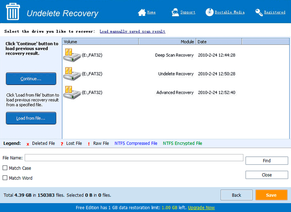
Screen Shot
System Requirements for NI LabVIEW Sound and Vibration Toolkit v4.0 serial key or number
- First, download the NI LabVIEW Sound and Vibration Toolkit v4.0 serial key or number
-
You can download its setup from given links:

NI LabVIEW Sound and Vibration Toolkit v4.0 serial key or number & Serial Key Download

NI LabVIEW Sound and Vibration Toolkit v4.0 serial key or number& Software